Hi,
I'm working on a balun for bandpass applications.
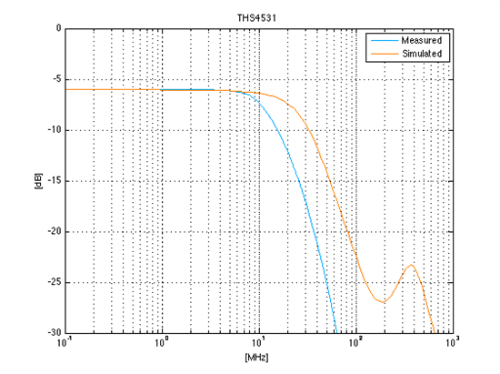
I have chosen the THS4531 for a conversion of a single-ended signal to a differential signal. The datasheet promises a 3dB bandwidth of 36 MHz at a gain of 1. I simulated the given test circuit with TINA and the TI-TINA model (figure 68 in datasheet). The result of the gain is shown below (orange line). In the simulation the THS4531 reaches a bandwidth of 30 MHz. As a second step I have built the schematic on a pcb. The measured gain (blue line) has a bandwidth of approx. 13.8 dB. For my application I need a bandwidth of 22.5 MHz. Now, my questions are as follows:
- Is it reasonable that even the simulation does not reach the promised 36 dB?
- How can the difference between simulated and measured results be explained?
- Is Texas Instruments able to build a pcb that fulfills the requirements?
- The simulation works up to a single supply voltage of 3 volts. At higher voltages the simulation collapses. Why? Is this effect based on the TINA model provided by TI?


