This thread has been locked.

If you have a related question, please click the "Ask a related question" button in the top right corner. The newly created question will be automatically linked to this question.

XTR111 DAMAGE ISSUE

Other Parts Discussed in Thread: XTR111

Hi,

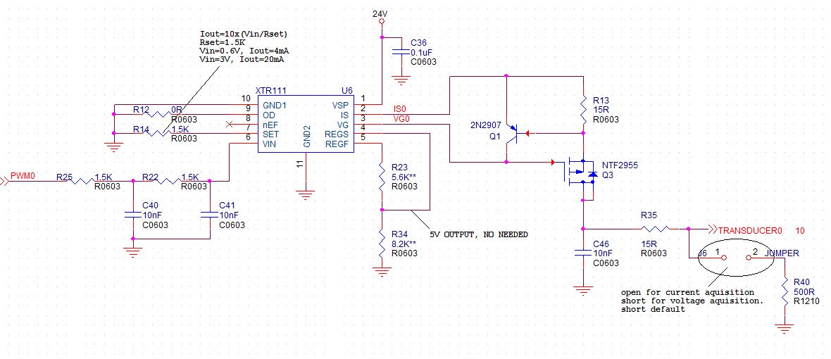
I'm now debugging my new design with XTR111, unfortunately the XTR111 is always damaged.

Here is my schematic.

Some times when I power on the board, then I found the chip XTR111 has been damaged.

Some times it seems work well, I can get a precious current output. Then I remove both the loads of regulator and the current loop, just power on the board and wait, several minutes later, the chip is damaged as well.

Is there anyone can give me some advice?

Thanks a lot.

Cloud Hu

GE Oil&Gas

  • Hi Cloud,

    Your schematic looks pretty simple and standard so at first I'm not seeing what would be causing damage to the XTR111.  The only thing missing from your design is the recommended capacitor on the REGF output.  Place a 470nF capacitor from the REGF output to GND to ensure stability of the internal voltage regulator.  Otherwise you've decoupled your supplies, connected the PowerPAD to GND, protected your inputs/outputs, so I will need some more information to determine what is damaging the device.

    Are you operating at room temperature?  Is there a long cable or any chance that powering on/off the system causes a voltage transient on the supply that violates the absolute max ratings?

    What are the signs or symptoms of the damaged XTR111?  Does it get hot, draw too much current, stop responding, etc.?

  • Hi Collin

    In fact I put a 0R resistor between REGF and REGS, and 0.1uF capacitor (I donot have a 470nF capacitor on my hand)  between REGS and GND. I also put a 5K resistor between REGS and GND to simulate the load.

    The regulator in my design is useless, I just use this function to judge if my chip works well.

    I used to test the power on waveform of 24V VSP, and I didn't find any pulse exceed the absolute max rating. I also have the ripple test of both VSP and Vin, they are pretty good, around 30mV.

    I test my board in a AC room with a temperature of 24℃, and the surface temperature of chip is around 30℃ when the chip is damaged.

    When the chip is damaged, the output regulator will increase slowly, both the REGF and REGS have the same voltage, and finally will reach around 22V. And I can't get the current output when the chip is damaged.

    It's really hard to hand solder the PowerPAD(thermal pad?), so I didn't connect the PAD for every chip. But I used to think the disconnection of PowerPAD may cause the damage, so I try to solder the PowerPAD for several chips, but no one can survival, they have the same phenomena.

    If it's convenient, can you please contact me by hailong.hu@ge.com? I'd like to share my layout to see if there is any potential issue.

    Thanks a lot.

    Cloud

  • Hi

    I just did another test. I disconnected the resistor of OD pin to turn off the current output, and removed the singal of Vin. That means the circuit just has a power input of VSP and 3V output of regulator.

    As I mentioned in the previous post it was really very hard by hand sordering so I didn't connect the Thermal PAD on the bottom of the chip.

    I kept on powering the  circuit for a while, and then the chip was damaged.

    I don't know when the chip was damaged because the value of current display on my DC power source didn't vary. I just checked the output of regulator 1 hours later then I found the output had increased to around 13V.

    I believe it isn't caused by some thermal issue because the input current is less than 1mA.

    Thanks a lot.

    Cloud

  • Hi Cloud,

    The symptoms you've described sound like a schematic or layout issue possibly due to a poor or wrong connection.  I sent you a direct e-mail so you can send your PCB information to us for review.