Hi All,
A square wave signal generated by FPGA which frequence is 5MHz,amplitude is 3.3V,and the current is 4mA.
Because of the low output current of FPGA,so I use a CFB to increase it.According to datasheet,THS3201 or OPA695 will be regarded the better choice for my application.
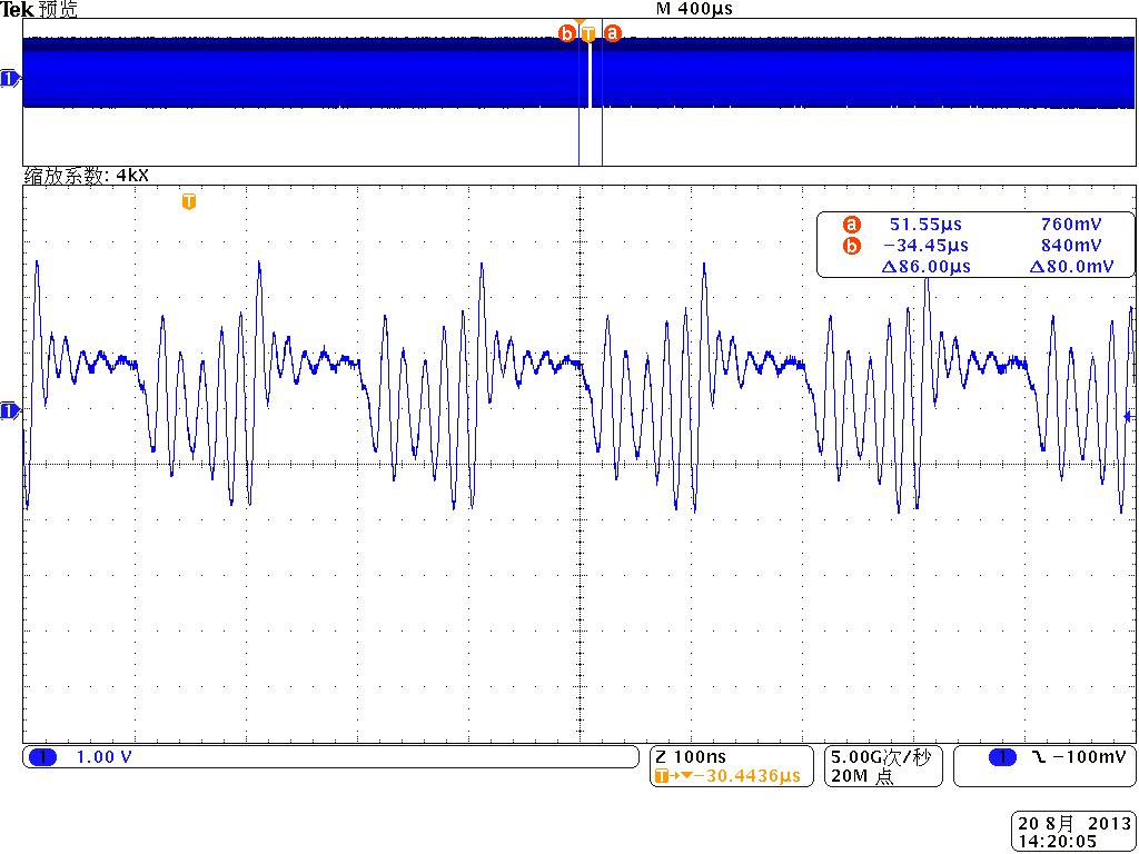
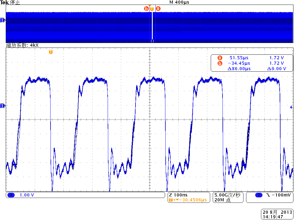
I set up my circuit based on datasheet. However,no matter which one I choose,the wave of Inverting input are very different from the Noniverting input one,you can find it from my Fig 2 and Fig 3.In theroy,the wave of Inverting input and Noniverting input are similar.
PTN78000AAH and PTN78000WAH play power supply module of the roles for THS3201 and OPA695.
Could you give me some suggestion about the matched resistance? And whether I need to pick up the LOAD during in my measurement?
Best regards
Penn
Schematic:
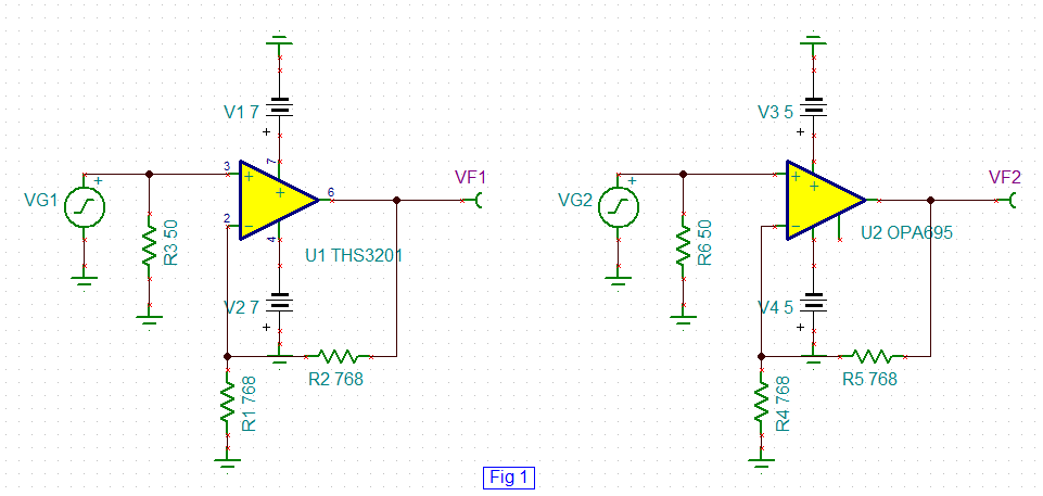
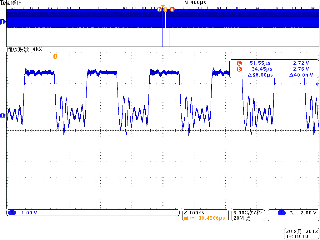
Fig 2 The original square wave signal