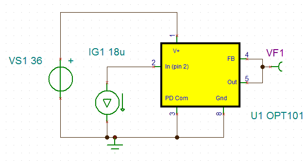
How do I simulate the light source in Multisim 11. I am attempting to design a laser frequency detector @780nm with the OPT101, my question to this forum is how do electrically connect the chip in multisim to simulate the light source?
This thread has been locked.
If you have a related question, please click the "Ask a related question" button in the top right corner. The newly created question will be automatically linked to this question.
Pete,
Below is the TINA Model hooked up to a current source that stimulates the device within the operating range.
IG1 is 18uA and the internal feedback resistor is 1Mohm, so the projected output is 18V. I did a little exercise by sweeping the current input of the device model and the plot is below.
I hope this helps you with your Multisim simulation.
Jason Bridgmon
Jason,
Thanks for replying to my post. I have the OPT101 and 301 imported into Mulitsim. Now I would like to perform a current sweep (AC analysis) to verify my circuits bandwidth. Using the circuit design that you provided (Figure 4 from the data sheet) I should get a -3dB cutoff frequency of 14 kHz.. This is not the case. What should my current value be at to replicate theses results and at what potential should I have pin 1 at?
Hi Pete,
Can you share your simulation schematic and an image of the results you observed? All of my simulation attempts this morning resulted in the correct result. The bandwidth is determined by an RC circuit in the model and works under all conditions...one thing I noticed in my simulations was that if you saturate the output (i.e. if the DC level of input current multiplied by the 1M transimpednace exceeds the output swing capability) the model will simulate a reduced bandwidth and reduced transimpedance...so if you are seeing a reduced bandwidth, please check that your output is not saturated into the positive rail while running the AC analysis. I simulated under the full range of power supply voltage (2.7 to 36V) with no issues.
Ed/Jason,
First off I will apologize for my stupidity, I am an Aerospace engineer thrown into this project to measure the frequency and intensity of a laser, and ultimately build a control system to stabilize it. So I am going to be asking a-lot of dumb questions on this forum.
I got the simulation to run correctly. Thank you for the quick replies.
In Jason's schematic he has 18 micro amps of current to stimulate the diode; where is that derived from?
I would like to build a detection circuit with either the 101 or 301 to give me a 5 mega hertz band width; is this possible? Do I need a second op-amp stage to achieve this?
Pete,
I selected 18uA because the internal feedback resistor is 1Mohm, and 18uA*1Mohm is 18V, which is right in the middle of the 36V range. I selected it purely for demonstrative purposes; there is no correlation to the physical world.
Regarding the OPT101 bandwidth; with 1Mohm as the feedback resistor, it is only 14kHz, per the datasheet. The OPT301 datasheet says the bandwidth for that part is only 4kHz. Also, keep in mind that the OPT301 is not recommended for new designs and was replaced by the OPT101.
Jason
Hi Pete,
No worries and no need for an apology we appreciate your questions. The schematic Jason used had a power supply voltage of 36V...after some discussion with Jason I decided if we wanted to simply demonstrate a simulation result at 36V supply, then we should probably use an 18uA DC input current which would place the output halfway through it's range, no particular reason to do this other than it seemed like a reasonable attempt...we could have just as easily chosen a 5V power supply with 2.5uA...or 1uA or 0ua to run the AC analysis. When running an AC analysis the circuit simulator first determines the operating point, then linearizes around that operating point and performs the AC sweep...so as long as you choose a valid DC operating point the AC response should be good to go. I actually am the Design Engineer for the OPT101 and am always happy to support the device.
In your case neither the OPT101 or OPT301 will achieve a 5Mhz BW under any biasing circumstances...so we must recommend a different solution...the best route to go will be to use a discrete photodiode and opamp...the choice of opamp will depend quite a bit on the amount of input capacitance that comes from the photodiode and any cabling that might be used in your system to connect the photodiode to the amplifier. It will also depend upon the feedback resistor value...you will probably not end up witha 1M Ohm transimpedance, but maybe a 1k ohm to 10k Ohm...for a starter please have a look at the OPA380...this amplifier can be used at 5MHz with 1k transimpednace with photodiode capacitance of 100pF...depending upon the overall combination of transimpednace, BW and noise requirements you may need to just use a discrete photodiode and discrete opamp.
It might be best that you repost your question in the form of 5MHz photodiode transimpedance amplifier needed and here are the requirements that must be met...and it would be most helpful to have identified the photodiode and the amount of input capacitance it will present. In this way the opamp experts can jump in and assist with pointing you to all their application notes regarding this topic of photodiode amplifier design. We have tons of materials to share :) The opamp applications engineers will have just the right app note for you, I am certain of it...
Ed/Jason,4174.5MHz BW Circuit results.doc
Thanks for your replies. I have a design achieving almost 1MHZ BW (attached). I am using a LMH 6702MA and a LM 6132BIN. I will work on this design today to increase the bandwidth. I will return next week to post the details of the circuit and some new questions under 5MHz photodiode transimpedance amplifier