Hi, I have a question. To a specialist, it may be an easy problem.
I built a simple circuit for sine wave generation and amplification of V_pp
and V_offset, which can substitute expensive function generator and linear amplifier.
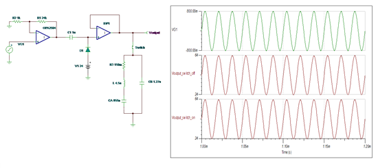
As shown below, 60kHz square wave generated from micro-controller is converted into sine wave by filtering out
all the higher-order harmonic components except 60kHz (>50dB extinction). Then OPA2604 amplifies the p-p
voltage (~20V_pp), and clamper circuit helps add offset voltage(~20V_offset).
It worked very well when I measured it with an oscilloscope. I could adjust V_pp and V_offset using two
trimpots very easily, stably and separately.
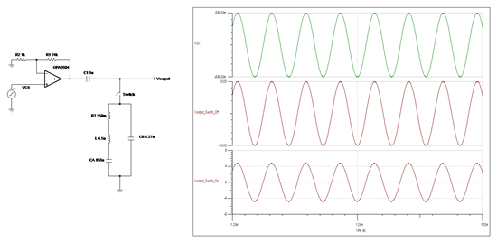
But, after connecting it to a targeted PZT component, the V_pp was limited only up to ~4V_pp at higher
voltage setting while V_offset is still well adjustable as before.
In this case, V_pp after the op amp is also clamped, and slightly distorted at high voltage setting.
For reference, I could find an equivalent circuit of a similar PZT component.
Desired range is 0-10V_pp and 0-15V_offset @ 60kHz sine wave.
Can anyone help about this problem and the solution?
reflection, impedance matching, power consumption, capacitive loading,....
Thanks in advance. cs.


