This thread has been locked.

If you have a related question, please click the "Ask a related question" button in the top right corner. The newly created question will be automatically linked to this question.

Inverting amplifier using OPA657

Other Parts Discussed in Thread: OPA657, LMH6702, OPA847, LMH6629, TINA-TI

Hello everyone,


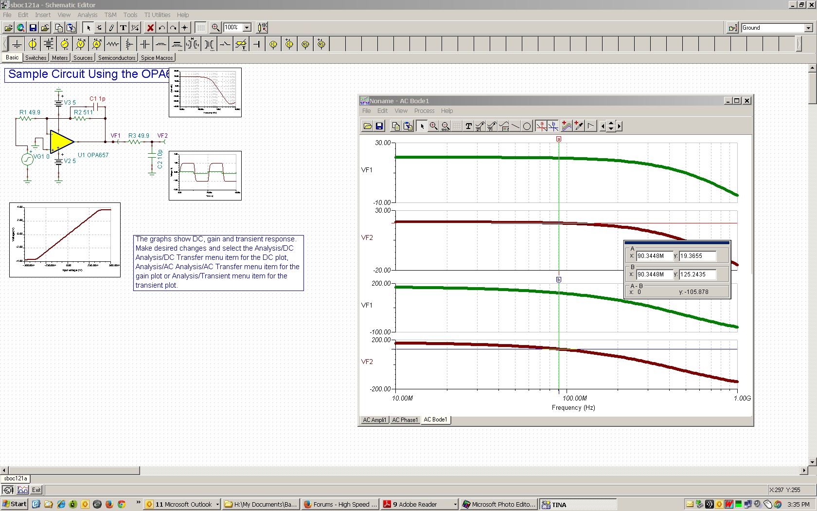
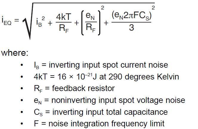
I was using OPA657 to amplify a high frequency signal from 10MHz to 90MHz. I bought several evaluation boards from TI. And I made an inverting amplifier of which the gain is 10V/V. The feedback resistor I used is 511ohm and Rg is 51.1ohm. The graph is the same as Figure 2 of OPA657 datasheet on page 10. I changed the conformation of oscilloscope probe. I took off the ground clip and used a very short wire as ground. The shape of amplified signal is good, I mean there is no obvious distortion in output sine wave. But I found when I increased the frequency from 10Mhz to 90Mhz, the gain is reduced. And I can see significantly phase shift on oscilloscope, from beginning nearly 180 degree to 80 degree at 90Mhz. The circuit seems to work as a low pass filter. So could anyone help me to solve this problem? 

Thanks!

  • Hello Feixiao,

    You will get some phase shift at that frequency. TINA shows that your circuit (Av= -10V/V, Rout = 50ohm looking into 10pF scope capacitance) should have 55 deg. of phase shift at 90MHz (compared to low frequency) (reading 125.2 deg.).

    Also, if your output swing approaches 2.5Vpp at 90MHz, you will start hitting the slew rate limit of the part (700V/us). May be you are measuring a lower swing because of slew rate limitation? Otherwise, the small signal amplitude should only drop by 0.7dB from low frequency (19.36dB reading).

    Regards,

    Hooman

  • Hello Hooman,

               Thank you very much for your reply. As you said, it might be correct. I was also using TINA to simulate some circuits behavior in high frequency. I can always see the phase shift but it seems the gain remains constant. I also think the amplitude of my signal itself might not be constant during the frequency changing from 10MHz to 90MHz. One more thing is I must compare the phase difference between two signals. However, because using opamp will generate phase shift, this could be possible that the phase difference between the original signals is 0 while after amplifying, it changes to a certain value, say 50 degree. So could you provide me some suggestions about how to cancel this influence or how to calibrate the circuits? Thank you!

    Best.

    Feixiao

  • Hello Feixiao,

    Sounds like you are building an amplifier to process 10MHz- 90MHz signals which causes negligible phase shift by itself. I'm not sure how that can be achieved. For example, here is the LMH6702 (1.7GHz bandwidth)  phase response and the phase shift delta between 10MHz and 90MHz is around 30 degrees:

    LMH6702 Gain / Phase Response:

    So, I'm not sure you can get a setup with "very small" phase delta (although I'm not sure what accuracy you are looking for?).

    To reduce additional phase delta, avoid probing with a 10pF 10x scope probe (with a series output resistance, say 50ohm, for isolation) as that adds additional phase delta. Instead, use a series output resistance (e.g. 50ohm) and go the scope 50ohm termination instead.

    If you have to use an amplifier, use a high speed one (like you are already doing) but run it at a low gain (to maximize its bandwidth). A current feedback amplifeir (CFB) like LMH6702 is less sensitive to gain increase.

    May be you can have a "look up table" of phase shift vs. frequency which then can be used as a baseline to look for phase shift delta computation.

    Regards,

    Hooman

  • Hello Hooman,

               Thanks again for your reply. I will introduce what we want to do. So this might be little bit longer. We want to accurately measured the phase difference between two signals. One signal is directly from the source. The other one is from PMT, a light detector. So I need to construct a transimpedance amplifier to amplify the current output from PMT. Because I am quite new for the high frequency measurement, so I made a circuit like the graph shown below just for experiment.

    0216.2013-10-2 18-31-40.tif

    I simulated using TINA and found the phase shift in 90MHz is around -60 degree. This seems correspondence with what I observe on oscilloscope.  The circuit I used to amplify the output current of PMT is like this:

    6330.2013-10-2 18-37-13.tif

    I also simulated this circuit using TINA. This time the phase shift in 90MHz is approximately 80 degree. That is to say if I use this circuit to amplify the current output from PMT and compared the phase difference between the original source output. I must subtract the phase shift generated by the circuit. Thus I am really not sure at beginning whether this phase shift is error or the circuit behavior is in fact like that. 

    Now several questions again. In your reply, you suggested me use a series resistor to isolate the probe and the circuit. I want to know if I could use, say in graph 2 R4, as the isolated resistor in order to measure the output of the amplifier or use another 50ohm resistor. Another question is, actually the circuit shown in graph 2 doesn't work. When I connect the input of the circuit to PMT, the current source should be PMT, it will have ringing on the output even if I didn't turn on PMT. I think there might be some mismatching between the impedance of circuit and PMT. But the C3 I used is based on the data from the PMT. So could you provide me some suggestions on how to cancel this ringing? For the maximum output of the PMT is just 10uA, so I don't think it is possible to use the opamp such as LMH6702 as you suggested because of its input bias current seems too large for our application. I select OPA657 and OPA847. Thank you so much!

    Best,

    Feixiao

  • Hello Feixiao,

    Some phase shift from your amplifiers is to expected at 90MHz (and less shift at 10MHz). You may be able to design an analog circuit to equalize the phase shift (assuming it is a constant from device-to-device), but I'm not an expert at this and cannot recommend anything right now.

    Below I'll try to answer your specific questions:

    1. In your reply, you suggested me use a series resistor to isolate the probe and the circuit. I want to know if I could use, say in graph 2 R4, as the isolated resistor in order to measure the output of the amplifier or use another 50ohm resistor.

    Answer: R4 is fine for isolation. My point was that you don't want to hang too much capacitance (cabling) directly on the output of a high speed amplifier. My other point was that any shunt capacitance after this isolation resistor may cause additional phase shift.

    2. Another question is, actually the circuit shown in graph 2 doesn't work. When I connect the input of the circuit to PMT, the current source should be PMT, it will have ringing on the output even if I didn't turn on PMT. I think there might be some mismatching between the impedance of circuit and PMT. But the C3 I used is based on the data from the PMT. So could you provide me some suggestions on how to cancel this ringing?

    Answer: The compensation cap of 2pF across your feedback resistor (R1= 1k) seems excessive. Since OPA657 is not unity gain stable, having too large a comp cap could get you in trouble. You could use Eq. 8 from the LMH6629 datasheet to find the optimum capacitance (it is usually a sub-1pF value). Here is a bit more detail:

    http://www.ti.com/lit/an/sboa122/sboa122.pdf

    For a non-unity gain stable device (like THS4021), in Figure 2 shown below, you just have to make sure that the intercept point (ideally at Fo) is at a frequency where the open loop gain is higher than 20dB (10V/V). If you increase CF too high, you may move P1 too far to the left that this could be violated. In most cases, a non-unity-gain-stable amplifier is not an issue for a TIA configuration.


    3. For the maximum output of the PMT is just 10uA, so I don't think it is possible to use the opamp such as LMH6702 as you suggested because of its input bias current seems too large for our application. I select OPA657 and OPA847.

    Answer: I only mentioned the LMH6702 because it had the phase vs. frequency information. I was not talking about your transimpedance amplifier either but instead your gain stage that process the TIA output. Also, if you have to use a large gain, a Current Feedback amplifier (like the LMH6702) will generally have less speed impact when you operate the TIA post amplifier (where phase comparison is actually to be made) at higher gain.


    Regards,

    Hooman

  • Hello Hooman,

               Thank you for your reply. Sorry for the late reply to your new response for I'm busy with other things this week. I want to finish the design step by step. So this is my first step of experiment. I designed a TIA using OPA657 and I will try your suggestions but I don't order the amplifier till now. The graph is shown below:

    2577.2013-10-9 12-28-38.tif

    Then I use an oscilloscope to directly detect the signal, the capacitance of the probe is 12pF. It is stable and the cutoff frequency of the circuits is similar as simulation. The problem is I found that there were some noise on the output signal. If I use the average function of oscilloscope, the signal looks pretty good, shown in graph below:

    7065.2013-10-9 12-34-04.tif

    Without using the average function, the waveform looks like:

    7522.2013-10-9 12-35-43.tif

    From the simulation of TINA, the noise level in this frequency seems less than 1mV. So do you think this noise comes from oscilloscope or other place? Thanks!

    Best,

    Feixiao

  • Hello Feixiao,

    The waveforms you have supplied do not represent random noise as they seem dominated by a 20MHz 10MHz (2 division at 50ns/div period) component and look to be around 50mVpp (which is too much to be random noise).

    You are either picking up this 20MHz 10MHz somewhere and amplifying it (or possibly getting it through your power supply, ground), or your circuit is starting to look unstable at around this frequency (this one would be my guess). To eliminate the latter, I propose that you test circuit with the setup shown below and using a lab generator (of at least 50MHz bandwidth or greater with at least 5V swing at R1 to get a 100mV peak output swing) to see if your output shows any excess step overshoot or ringing or sine wave peaking? These symptoms would indicate that you'd have to compensate your TIA to make sure you have more phase margin.

    Your setup does not mention the photodiode capacitance (but that should be included / added to match the actual setup).

    If you have not seen the application note and E2E post below, please take a look at these as well:

    http://e2e.ti.com/support/amplifiers/high_speed_amplifiers/f/10/p/294380/1029567.aspx#1029567

    http://www.ti.com/lit/an/sboa122/sboa122.pdf

    Regards,

    Hooman

  • Sorry: I meant to say a "10MHz" and I said "20MHz" component above, by mistake.

    Regards,

    Hooman

  • Hello Hooman,

               I think I may express the problem wrong so this might mislead you. The signal output of the detector should be a sine waveform because I use a sine wave to modulate the light source. As you see in the first graph, I attach it again here:

    8244.7065.2013-10-9 12-34-04.tif

    This waveform should be correct. However, I used a function of oscilloscope to filter the original waveform to get this signal shown on the above graph. It is one 16 point average filter. Without filtering, the waveform looks like that:

    8838.7522.2013-10-9 12-35-43.tif

    You can see small noise overlapped on the smooth signal. The amplitude of the signal is about 10mV. So I just wonder how this noise comes from. Oscilloscope probe or other place? Besides, the output capacitance of detector is 22pF and the internal resistor is 10Mohm. Thanks!

    Best,

    Feixiao

  • Hello Feixiao,

    The un-averaged waveform "noise" riding your sine wave looks a bit non-random (periodic) with about a 0.4 division repetition rate (~50MHz). A spectrum analyzer would probably be a better instrument here to see if you have any spurs there or not? A spectrum analyzer capture would also confirm whether you are dealing with a periodic spur or a random phenomenon.

    If you are dealing with random noise, below is the expected output noise for your conditions:

    The expected input referred current noise can be shown from Eq. 13 from:

    http://www.ti.com/lit/an/sboa122/sboa122.pdf

    The last term derivation (if you are curious) can be found here:

    http://e2e.ti.com/support/amplifiers/high_speed_amplifiers/f/10/p/257049/899977.aspx#899977

    For the OPA657:

    en= 4.8nV/RtHz

    iB= 1.3fA/Rthz (negligible)

    Cs= 22pF + 5pF parasitics= 27pF

    RF= 10k

    4kT= 1.6E-21J at room temp.

    F= assume 10MHz (10k and 1pF result in 16MHz bandwidth)

    iEQ= SQRT( (15fA)^2 + (1.6E-21/ 10k) + (4.8nV/10k)^2 + (4.8nV*2*pi()*10E6* 27pF)^2/3) = SQRT(0 + 160E-27 + 230E-27 + 22.1E-24) = 4.74pA/RtHz (this is dominated by the last term!)

    So, the RMS output noise will be:

    Vo_noise_RMS= 4.74pA/RtHz * 10k * sqrt (10MHz * pi()/2) = 188uA_RMS

    With the scope vertical scale you have shown (50mV/div), this RMS noise (or 1.2mVpp) will probably not be visible! So, I do recommend you look at your closed loop response (possibly using the current source technique I sent earlier) to make sure you're not dealing with lack of phase margin which could result in small amplitude oscillation resembing noise on your waveform.

    Regards,

    Hooman

  • Hello Hooman,

               I tested the circuit as you suggested. There are several problems. One problem is I can see the ringing on the output of the amplifier no matter what value Cf I used when I powered the circuits without input signal. I tried 1pf and without using the cap. But this ringing is not a whole sine wave, please see the waveform in the graph shown below:

    Then I turned on the 'lab generator', actually I don't have such higher frequency function generator in the lab. I just use a source to drive LED which can output the voltage signal up to 100MHz. It can amplify the signal without using Cf but it seems in low frequency (<30MHz), it can not amplify. Using 1pf Cf, I can not see anything except the waveform of noise (the amplitude is larger). So could you give me some suggestions on how to cancel the noise or do you think it is because in order that I could construct the circuit as you said, I must  use a bread board to pre-process the voltage signal to get the current signal, in this procedure, I could have more parasitic cap. Thanks!

    Best,

    Feixiao

  • Hi Feixiao,

    I bread-boarded the OPA657 as a transimpedance amplifier (gain = 22kV/A) and tested it with a bench generator and I got good results + no instability.

    Here is the TINA-TI circuit which simulates closely with the measured results:

    5432.OPA657 TIA Circuit Bench Testing 10_21_13.TSC

    Here is the resulting step response showing a rise / fall time of close to 31ns (about 10MHz -3dB BW).

    If I were using an actual photodiode as the source, I might have gotten closer to the ~50MHz ~30MHz bandwidth which is what you'd expect (RF= 22k, Cj= 10pF). As you can see, I've used a large cap for C3 (6.8nF) across the input termination to compensate for the parastic cap of the 510k resistor (R4) I've used on the input to mimic a current source.

    Most importantly, I don't see any ringing or oscillation.

    I used the OPA657 EVAL unpoppulated EVAL board for my bench testing:

    http://www.ti.com/tool/dem-opa-sot-1a

    Please review and let me know if you have any questions?

    Regards,

    Hooman

  • Hello Hooman, 

              Thank you very much for your help till now. Unfortunately, my amplifier still doesn't work. Anyway, I will try to buy some more to test it again. Just for one thing, normally what temperature is it when soldering this chip. Besides, I saw you used a very small capacitance (500fp etc.). I just wonder whether it is a real cap or you just simulated the parasite cap in the circuit. Thanks!

    Best,

    Feixiao 

  • Hello Feixiao,

    My responses:

    1. Small Capacitor: CF, the 500fF cap across RF is two 1pF SMT caps in series. It is in fact on my board. C2, the 300fF cap across R4 is added to simulate the parasitic capacitance I expect to be there (but it is only in the schematic / simulation to mimic expected reality).

    2. Soldering Temp: I normally set my soldering iron to ~850 deg. C when I bread-board.

    Hope you can resolve your issues. Let me know what you find out.

    Regards,

    Hooman

  • Hi Hooman, A quick question, why you said using the actual photodiode might reach higher bandwidth-30 MHz , and even the "fake pd" of the same 10pF cap could only reach 10Mhz. Because what I expect is, if you use the actual pd, the bandwidth could not higher than the mimicked pd since there is a cutoff frequency limit of pd itself. Br, Jason
  • Hi Jason,

    What I intended to convey about the actual photodiode circuit 30MHz expected bandwidth (using OPA657) was related to how I created an input current source to mimic the photodiode and how the finite current source impedance (510kohm) might affect the measured results. In addition, I used a large (6.8nF) cap across R3 (50ohm) input termination, in an attempt to create a flat response (using my estimate of the equivalent cap across R4 of 0.3nF). I meant to say that all this are differences with an actual photodiode setup, without these factors, which might affect the results.

    If the photodiode has its own inherent upper frequency reach (as you noted) which is low enough, obviously that would come into play as well and reduce the effective bandwidth.

    Regards,

    Hooman