This thread has been locked.

If you have a related question, please click the "Ask a related question" button in the top right corner. The newly created question will be automatically linked to this question.

OPA847 oscillation

Other Parts Discussed in Thread: OPA847, LMH6629, TINA-TI, OPA657

Dear all

I am designing  Transimpedance (TIA) amplifier with OPA847,  choosening because of its high GBW and smallest input voltage noise.

However, I got a problem about "stability".

Given by the feedback theory and simulation results  putting a small feedback capacitor in  parallel with feedback resistor should making the TIA more stable (at the cost of the lower bandwidth).

However, once the feedback is larger than certain value (For example 1.1 pF when feedback resister is 1.8k), the system starts oscillating.  If  I reduce the value feedback capacitor,  it start ringing. 

I found someone else also get this problem.  in http://e2e.ti.com/support/amplifiers/high_speed_amplifiers/f/10/t/38799.aspx

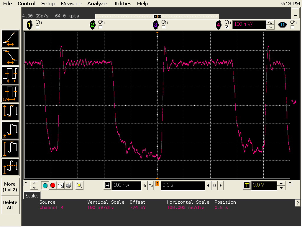
Here I attached two screen shot of my TIA. First one with big Cf, the system becomes unstable. Second with small feedback resistor,  the system starts overshot.

Any help on this matter would be much appreciated.

  • Hello Liu,

    One possibility is that since OPA847 is not unity gain stable, using too large a CF could be the cause for instability. Here is an E2E post with an application note and some notes within which may help you:

    http://e2e.ti.com/support/amplifiers/high_speed_amplifiers/f/10/p/293655/1025819.aspx#1025819

    In addition, here are some things which in the past have helped me stabilize a fast TIA, specifically when dealing with the LMH6629 in the TIA configuration which had the photodiode placed at a ~3" distant from the inverting input, as shown in the schematic below:

    1. A resistor (R6= 100ohm) in series with the inverting input to see if the instability is related to loop phase delay of R1 looking into the "Flex Board" (which is essentially a PC board with two traces on it with the net effect of moving the photodiode (not shown, on the left) further from the amplifier + its parasitics)

    2. An RC across the device inputs (I've used 55ohm in series with 1.2pF for R5 and C1)

    3. Placing R4 in series with the 1/2 supply decoupling cap (C3) so that the non-inverting input AC resistance is not zero (will be 1kohm instead in this case). I think of this fix as adding base resistance to high frequency BJT for stability

    Note that in my particular case, I have no cap across R1 (feedback resistor) as the parasitic capacitance of the 25k resitor (+ board) was enough to stabilize the loop. Your case may be different

    Hope these hints help you out.

    Regards,

    Hooman

  • Hi ,  Mr Hooman Hashemi

    Thanks for you quick answering.

    I put my  Tina simulation file here, are you saying that, though simulation shows that OPA847 can get a 3-db bandwiddh @ 100 MHz with 50 p photodiode capacitance and 2.5 p feedback capacitor, in reality, due to the unit-gain unstable, it will make system starts oscillation once the CF larger than 1 p?

    7762.847.TSC

  • Hello again Liu,

    I was only suggesting that if CF is raised too high, the following expression may cause the Open loop gain plot intercept with the Noise Gain plot to occur at below the minimum stable gain of the device (12V/V for the OPA847):

    From: http://www.ti.com/lit/an/sboa122/sboa122.pdf

    With the values you've shown in your TINA-TI file (Cs= 50pF, CF= 2.5pF), your setup shows a value of 21V/V which is above the minimum stable gain of the OPA847:

    20.log (1+ Cs/CF)= 20.log (1+ 50pF / 2.5pF)= 26.4dB = 21V/V

    You may run into this issue if CF approaches 4.5pF such that the expression above equals 21.6dB (12V/V). So, if your layout / parasitics adds much capacitance to CF, it is conceivable that you reach this critical value (4.6pF) with even a smaller CF (discrete component).

    So, with your present conditions (assuming a low parasitic setup / layout) your instability is not caused by the phenomenon I've tried to describe.

    Regards,

    Hooman

  • Hello Liu,

    Regarding my post on October 3 about trying the non-zero AC resistance to ground to see if stability is achieved:

    I've modified your TINA-TI file (with R5 and C4 on the non-inverting input) by adding the resistance R1 (100ohm in this case) to clarify what I mean (your original circuit showed R5=1.2k R1=0ohm which does not serve the purpose of raising the AC resistance):

    Regards,

    Hooman

  • thanks, Hooman, I will try to add R1, and give you feedback this afternoon.

  • Hi,  Hashemi ,

    shortly update 

    Good thing is adding a R1 in in the non-inverting node do helps.

    Bad thing is it does not help a lot.  

    Without R1,  i can increase cf to 1p unitil system unstable. with R1,  this value rises to 1.4p.   Still,  I can not reach the calculated unstable value (4p).

  • Hello Liu,

    I've tested a TIA using the OPA657 and got stable results using the SOT23 EVAL board. Your conditions are much faster due to much lower feedback resistor of 1k, but I wonder if there is anything here you can benefit from:


    http://e2e.ti.com/support/amplifiers/high_speed_amplifiers/f/10/p/293655/1038541.aspx#1038541

    Also, are you probing the OPA847 output directly with a passive scope probe? If so, I recommend avoiding that (may be by using the scope in 50ohm terminated mode with 50ohm series output for isolation).

    Have you pinpointed the reason for the slow fall time in the scope photo you posted on October 03, link below?

    http://e2e.ti.com/cfs-file.ashx/__key/communityserver-discussions-components-files/10/2548.max-bias.png

    I'm puzzled why the rise and fall times are so different (I can't tell your vertical scale, horizontal = 100ns/div). That may give you some clues if you are able to find out why. Is this large signal or small signal behavior with the photodiode proving the stimulus?

    Have you made sure your bread-board layout is not adding much capacitance (i.e. SMT components with minimal trace lengths, small value decoupling capacitors on both supplies to nearby ground plane, removing of ground plane under the sensitive node (including any inner layers), avoiding vias as much as possible, etc.). In my OPA657 test link above, I've used the TI SOT23 EVAL board.

    I'm just throwing out ideas that might help.

    Regards,

    Hooman