This thread has been locked.

If you have a related question, please click the "Ask a related question" button in the top right corner. The newly created question will be automatically linked to this question.

How to see the bode plot of a CFB

Other Parts Discussed in Thread: LMH6702, LMH6609, LMH6629

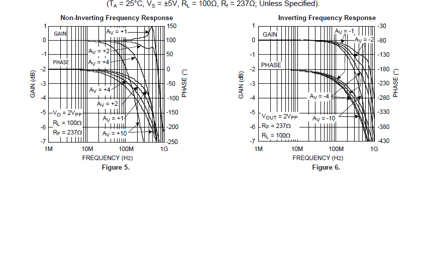
Hi,I am confused about the bode plot of the chip LMH6702,why the Y-axis is 1,0,-1,-2,...while the curves have been marked with Av=1,2,4,10? And how to see the bode plot? could you please help explain it carefully?

Thanks!  
  • Hello Carter,

    The vertical axis of the frequency response plots you have shown are "normalized gain" values. That is, for each closed loop setting (i.e. 1, 2, 4, or 10V/V), the plot shows the change in gain from low frequency to high frequency, but not the actual gain value. Most people look for the -3dB frequency. For 10V/V, as an example, that would be a little over 100MHz.

    The open loop Transimpedance response (which I think is what you call Bode plot) is shown in Figure 23.

    Regards,

    Hooman

  • Thank you very much!

  • Hi Hooman,

    Thanks for your answer,I have another two  questions and want your help:

    1.Is the Gain of a CFB opa smaller than a VFB opa?the VFB OPA gain can be hundreds of thousands,but I didn't see a high gain with a CFB OPA.

    2. I always hear of that the band of a CFB is not limited by the gain,but from the flot it seems that the higher the gain,the lower the band,why is it like this?

  • Hello Carter,

    My responses to your numbered questions below:

    1. Voltage Feedback gain vs. Current Feedback: In most cases, you will have more flexibility with voltage feedback devices if you need a very large gain. Current feedback feedback resistor range is limited and the gain setting resistor (used called Rg) cannot be reduced limitless without running into other issues. Plus there are noise implications as well. So, for really high gain stick with voltage feedback devices. If you are looking for high gain at large bandwidth, you can go with "uncompensated" (non unity gain stable) devices which are usually higher speed. LMH6629, and LMH6609 are a couple I know about.

    2. Bandwidth independence of Current Feedback devices: What you have heard has merits theoretically, but it is only a 1st order approximation of an actual device. This application note describes how the output impedance of the input stage buffer of a Current Feedback device (Ri in the application note below) causes bandwidth reduction at higher gains:

    http://www.ti.com/general/docs/lit/getliterature.tsp?baseLiteratureNumber=SNOA366&fileType=pdf

    http://www.ti.com/general/docs/lit/getliterature.tsp?baseLiteratureNumber=SNOA367&fileType=pdf

    However, the impact on bandwidth will generally be less than a Voltage Feedback device which reduces inversely with closed loop gain increase.

    Regards,

    Hooman