Because of the Thanksgiving holiday in the U.S., TI E2E™ design support forum responses may be delayed from November 25 through December 2. Thank you for your patience.

This thread has been locked.

If you have a related question, please click the "Ask a related question" button in the top right corner. The newly created question will be automatically linked to this question.

photodiode amplifier

dears all,

i am designing the photodiode amplifier but it is showing some oscillations . interestingly in the second stage if i reduce feedback resistor to 200k it there are no oscillations , why so ??. please suggest me correct way to find the feedback capacitor . please explain me about this circuit. Photo diode is reverse biased & output terminals are shown in circuit
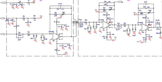
  • What are the Diodes for? cutting off the inputs at +/- 0,7V ?

    Is the first stage directly coupled via a C to the diode, I think this might cause the diode to get biased with a dc voltage, which might cause problems.

    Otherwise it is noisewise always better to get the whole current-voltage conversion done in one stage only, I think it should be possible since your gain-levels of stage 2 and 3 are not that high.

  • Suresh,

    The resistor and capacitor in the feedback loop of the amplifer create a pole zero pair. The zero is equal to 1 / (2 pi RIN||RF*CIN||CF) where CIN is the combination of the photodiode capacitance and the amplifier input capacitance. The pole is equal to 1 / (2 pi RF * CF). The magnitude of the feedback loop at DC is 1 + RF / RIN where RIN is equal to the photo detector's input resistance. The magnitude of the feedback loop at higher frequencies (beyond the pole and zero frequencies) is 1 + CIN / CF. It is important to make sure that the intersect frequency between the feedback loop curve and the open loop gain curve of the amplfier is higher than the pole frequency. You can adjust the pole frequency by changing either CF or RF. I recommend that you change CF.