This thread has been locked.

If you have a related question, please click the "Ask a related question" button in the top right corner. The newly created question will be automatically linked to this question.

Power Amplifier - Voltage Controlled Current Source for injection into power system

Other Parts Discussed in Thread: OPA541, OPA549

Hi, 

I am currently doing a power system project where I am required to implement a FACTS device to inject compensation current into a system. Due to the system being rather frustrating and lack of design knowledge of control, I was then advised that "to ensure a result" take the current compensation waveform and just use a power amplifier instead. The system is a non-linear load and can be seen below:

I currently have a control unit that analyses the system produces a compensation waveform. This waveform is outputted by the NI 9269 unit. This is a +- 10v analogue voltage output of 10mA per channel.

So i guess my question is this. The compensation waveform current has been calculated for the load as seen below:


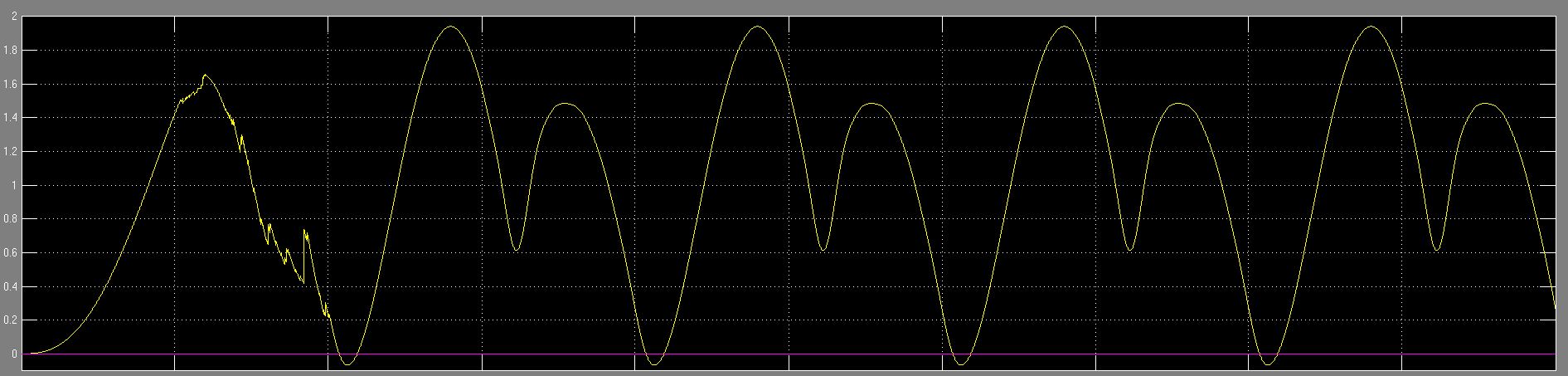
Is there an power op amp that I can:

1. Turn my voltage compensation waveform into current supply for injection to system

2. Boost the current to match the correct Amps needed

3. All while ensuring time is not lost on the system or at least not introducing a massive delay

I was looking at different op amps and voltage controlled current sources but am just needing a bit of guidance as to what products I should be looking to try to implement. I would obviously like to simulate the system when I can, but ultimately am looking for what type of amplifiers or set of amplifiers that would be needed to achieve this.

Any help would be greatly appreciated as I have been reading up on power amplifiers, but just feel I'm going around in circles.

Regards,

David

*EDIT* - I have been looking through and found the OPA549 and OPA541, would either of these amplifiers work with what I am trying to achieve and what type of configuration would be needed? - Voltage follower, voltage to current source,etc?

  • Hi David,

    You indicate that you need to inject current into the circuit which appears is intended to flow through the circuit on the right hand of your schematic. Therefore, a device inserted at the injection point would have to be able to deliver the required current into that load. The actual current in the load would be a function of the total load impedance and the drive voltage level (I = V/Z).

    There is a 28.87 VRMS, 50 Hz signal applied at the amplifier input according to the schematic. Assuming that this symmetrical about 0 V, the peak voltages would be +40.8 Vpk and -40.8 Vpk. Unfortunately, that exceeds the input level and maximum supply voltages for the OPA549 and OPA541. If the required current to the output load does not require such a high input voltage, then these operational amplifiers might be useable.

    I did a TINA Spice simulation of your circuit where the OPA549 model was included. I drove the input with +/-20 Vpk. You can see the corresponding output voltage and current waveforms. This may provide you some idea where you need to set the circuit conditions.

    Regards, Thomas

    PA - Linear Applications Engineering

    OPA549_PA_01.TSC
  • Hi Thomas,

    Thank you so much for your contribution. You have made things a lot clearer. I believe that the output from the CRIO device is max +-10v input into the system and i have been looking into Voltage Controlled Current sources, specifically the improved 'Howland current source pump' set-up. Have you had any experience in designing such circuits. To my understanding the cct. below works: theoretically/simulation and I'm about to build it. Any last ideas that i should be aware of. This is the first amp cct. i have built.

    Now obviously it isn't the OPA549T as I don't know how to add components into multisim and the current waveform compared to the voltage waveform are seen to be almost identical 1:1. which is what I'm looking for. any specific design requirements you see I have overlooked? I just have a switch mode power-supply i was going to use to power the op amp. I believe is a +-24Vdc. 

    Thanks again so much I think I'm starting to understand a lot better.

    Regards,

    DAvid

  • Hello David,

    It looks like you have made good progress finding a way to drive the complex load. I am indeed familiar with the Improved Howland Current Pump and have applied it a number of times in dc and ac current source applications. One of the most complete treatments on the current pump is a TI Applications Report created by the National group. You can find it here:

    http://www.ti.com/lit/an/snoa474a/snoa474a.pdf

    It provides about everything you would ever need to know when applying the pump. 

    I do note with your circuit is a bit unusual in that not only is there a generator at the input, but one at the output as well. It appears the pump circuit would force current not only through the complex load impedance, but through the output generator too. An ideal voltage source has zero internal impedance and would sink and source current. I do not know for certain how a real amplifier will behave if the output generator attempts to drive current back into the amplifier. Simulation models may not model this condition well. Also, the diode placed across a portion of the load changes the load impedance characteristics between the positive, and negative portions of the output swing. Just some things to keep in mind.

    Regarding the OPA549 simulation model, there is a PSpice version on the product web page. I checked the syntax in the OPA549.LIB file and it is straightforward PSpice. We have had good success when the syntax has been used with other simulators such as Multisim. You should be able to take that file, change the .LIB extension to whatever Multisim uses, associate a symbol that accommodates all of the OPA549 pins, and use it with the simulator. I don't have Multisim so I can't say for certain that it will work as I expect.

    Regards, Thomas

     PA - Linear Applications Engineering

  • Hi Thomas,

    Yes that was definitely a concern of mine, how the amplifier goes in parallel and I was also not knowing if the simulation would be adequate enough. I will have to wait and see. Thank you again for your help regarding this project.

    In terms of adding the OPA549 model when trying to add the component into MULTISIM, the model uses only 8 pins but I get an error with the spice code saying there is eleven pins. I believe this to be a multisim problem in reading the spice file, I'm a bit unaware how to add hidden pins. The text converted correctly however.

    Note: If anyone reading this has an OPA549 component for MULTISIM could you please send me the component model.

    On another note. If I was to now have to isolate the power system, I would now need to also isolate the amplifier. If this was the case would this be the setup i'm looking for: 

    Note: I'm talking about practical wiring. As in should the grounding of the -in of the op-amp go to the in put voltage waveform card (NI9269) or to the -ve of the isolation transformer that would be used. It is noted that: 

    The analog output channels are floating with respect to earth ground and each other on the (NI9269 Card).

    Idea1:

    Not too sure with this one. Simulation also gives a bit weird results.

    Idea two:

    Now I'm not too sure if it would work straight into the card in real life. Would it work to link the -ve input into a floating ground that is separate to the isolation card's ground? as well as the earthing of the system itself?

    Anyways,

    Thanks again, upon answer I will be building this weekend and I'll let you know how it goes. 

    Regards,

    David

  • Hi David,

    A lot to consider. The OPA549 model is defined by 11 functional pins. I extracted the syntax from the model:

    * CONNECTIONS:  VOUT

    *               |   VOUT

    *               |   |   INVERTING INPUT

    *               |   |   | NON-INVERTING INPUT

    *               |   |   | | NEGATIVE POWER SUPPLY

    *               |   |   | | |   REF VOLTAGE FOR CONTROL PINS (ES AND ILIM)

    *               |   |   | | |   |   NEGATIVE POWER SUPPLY

    *               |   |   | | |   |   |   CURRENT LIMIT ADJUST

    *               |   |   | | |   |   |   |   ENABLE/STATUS

    *               |   |   | | |   |   |   |   |  POSITIVE POWER SUPPLY

    *               |   |   | | |   |   |   |   |  |  POSITIVE POWER SUPPLY

    *               |   |   | | |   |   |   |   |  |  |

    .SUBCKT OPA549 OUT OUT2 - + V- REF V-2 LIM ES V+ V+2

    The (-) and (+) signs in the .SUBCKT line are node connections. So Multisim is correct in recognizing it as an 11-pin model.

    The Improved Howland Current Pump is essentially a difference amplifier. You have it set up for a gain of 1 Amp/ V. The output current will be the difference in voltage between the two generator sources, times 1 Ampere. If you take for example the difference between the peak voltages of the two voltage sources the difference is 32.8 Vpk. Multiplying that by the gain equation would result in an output current of 32.8 Amps - which none of our power operational amplifiers can supply. When you calculate the output voltage across the load for positive and negative swings the reversed bias diode condition would result in a 1 kV just across the 33 Ohm resistor.

    The generator driving both the inverting input circuit and the output caused big problems when I tried to simulate the circuit. I could not get the circuit to simulate even when using an ideal operational amplifier. Maybe an isolation transformer will resolve that issue, but there may be underlying circuit implementation issues that would prevent it from doing what you intend.

    Also, keep in mind your input and output swings and the operational amplifier supply requirements. You show the OPA512 using a single supply. It was never intended for single supply operation - only dual supplies. Your simulations will give you erroneous results if you use a single supply with it.

    My suggestion is you use an ideal operational amplifier model initially and get the circuit working in simulation as you need it to work. Then, incorporate the model for the operational amplifier you intend to employ and power it accordingly. Once everything appears to be working correctly you can evaluate the different isolation schemes.

    Regards, Thomas

    PA - Linear Applications Engineering