This thread has been locked.

If you have a related question, please click the "Ask a related question" button in the top right corner. The newly created question will be automatically linked to this question.

INA128 bandwidth

Other Parts Discussed in Thread: INA128

Hi there,

I am currently testing the INA128 and I am a little bit surprised because above 50Khz a sinewave input signal is turned into a triangular one. In other words my input signal is distorted. 

Is it a nominal behaviour ? According to the spec sheet, the BW is around 1Mhz with a unity gain.

Thanks in advance.

Paulo.

  • Paulo,

    It sounds like you are observing slew-rate induced distortion. With a 50kHz sine wave input, at some finite amplitude, the output will experience slew-rate induced distortion. This concept is sometimes refered to as full-power bandwidth (directly related to slew-rate).

    To better understand your observed distortion, would you mind providing us with more information about your input and output signal amplitude and frequency? A schematic or detailed description of your testing setup could also help us rule out other factors and understand the distortion you have observed. Thank you.

  • Hi Michael

    here enclosed you'll find the model I used. It describes exactly the way the OPAMP is wired on a breadboard.

    The amplitude is ±16V pk and the INA128 is powered up to ±18V. Then I sweep the frequency.


    I was expecting to reach at least 1 Mhz, as depicted, here below, for an unity gain:

    Best regards.


    Paulo.

    INA128_distorted output.TSC
  • Paulo,

    Operating the device (G=1) with a 32Vpp, 80kHz output signal exceeds the slew-rate of the device.

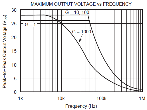
    The INA128 datasheet curve showing full-power bandwidth (max output vs frequency) is shown below.


    The curve shows the maximum output voltage vs. frequency for a sine wave signal. The curve is specified for a Vs = ±15V. Typically, an output signal operating above and to the right of the curve will experience slew-induced distortion (output signal will exceed the slew-rate of the device).

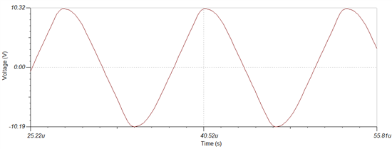
     Using your TINA simulation, I adjusted the input signal to a 20Vpp, 80kHz sine wave. This results in the output operating slightly above and to the right of the G=1 curve. As expected slew-induced distortion can be seen in the output as shown in Figure 1. Significant distortion (triangle wave) will appear as the slew-rate is exceeded further.


    Figure 1: Slew-induced distortion at 20Vpp, 80kHz.

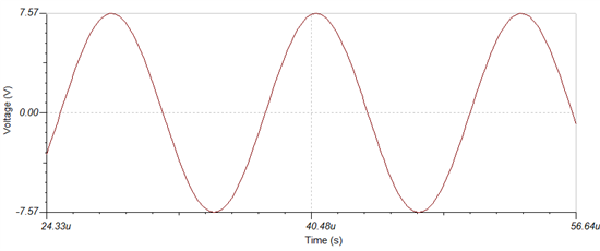
    To avoid slew-induced distortion for a signal at 80kHz, the G=1 curve shows to decrease the output amplitude below approximately 16Vpp. At 15Vpp 80kHz, the slew-induced distortion is removed and the simulated output is shown in Figure 2.

    Figue 2: No slew-induced distortion at 15Vpp, 80kHz.

    As shown, the slew-induced distortion decreases when the output operates below and to the left of the datasheet curve (not exceeding the slew-rate of the device). Although these are simulated results, you expect to see similar behavior when testing the device on your breadboard.

  • Hi Michael,

    now it is very clear.

    Thanks a lot for your support.

    Cheers.

    Paulo.