This thread has been locked.

If you have a related question, please click the "Ask a related question" button in the top right corner. The newly created question will be automatically linked to this question.

photodiode current sensor circuit(laser range finder using phase difference method)

Other Parts Discussed in Thread: OPA656

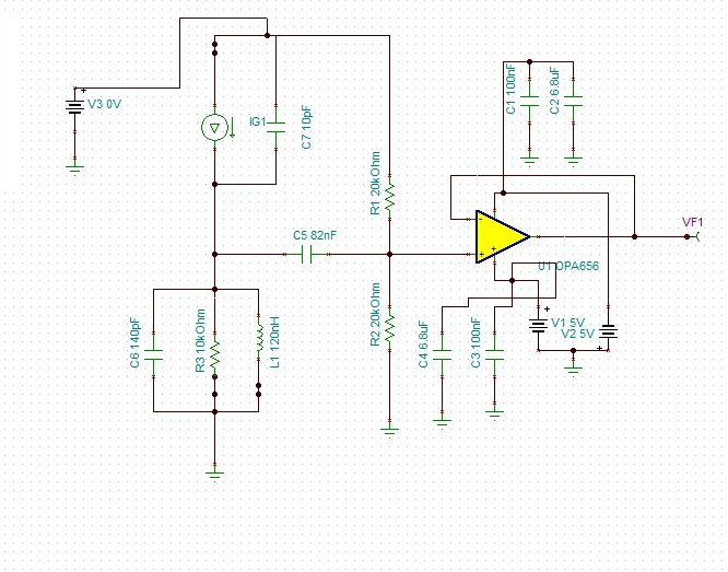
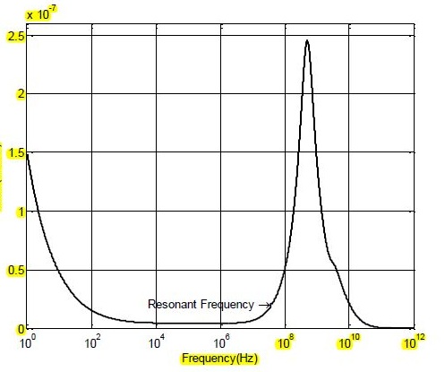
these two up side given diagram output i want get .my output is not diserable please help me choosing correct coponents values.this my design using OPA656

.1663.current sensor potodiode amplifier.TSC

please set my output.please 

t

  • my required resonant frequeancy is 37.5MHZ. BANDWIDT IS 37.5MHZ.

  • Hello,

    I noticed that you have not received a reply to your E2E post. I tried to provide a response but I was not exactly sure what your question or issue is.

    Could you provide more information as to how you would like the circuit to behave and what exactly is the response you are looking for?


    Regards,

    Hooman

  • thanks Hooman for reply

    i am using opa656 for differential output .i want sense the phototransistor emitter current and amplify using opa656 .i want built a differential amplifier to sense phototransistor current and .

    i am working on laser Range finder triangulation method .

    i want amplify the photodiode or phototransistor current and run a servo or stepper motor to foscuse te laser beam on PHototransistor.so kindly help me

    design a differential amplifier using opa656

    regard 

    EMMR

  • Hello EMMR,

    I tried to follow your circuit and see if I can help. However, I still cannot understand many of elements. For example:

    1. Why are you using the OPA656 with 0ohm feedback resistor when your signal from the photodiode is so small (nA)?

    2. What is the purpose of R1, R2 (20kOhm) on the input? These relatively low values lower your circuit's input impedance to 10kOhm, while you've chosen a JFET input device (OPA656) which I presume was to have high input impedance? For DC biasing, you could have chosen much higher values

    3. What are the elements L1, R3, and C6 representing?

    4. Is the resonance you are speaking of on the input due to the inductor L1 and the capacitance it sees? Is this resonance something you are interested in, or is this something you are trying to get rid of? If you are trying to get rid of it, what things can be modified or moved around to achieve that?


     Sorry, I have more questions than answers. May be somebody else who can understand your question / application better can jump in here and help.


    Regards,

    Hooman

  • Hello EMMR,

    There might have been a problem with E2E on Monday 12/23/13 related to sending out emails with posts.

    I've posted some questions to see if I can help you better.


    Regards,

    Hooman