A related question is a question created from another question. When the related question is created, it will be automatically linked to the original question.
If you have a related question, please click the "Ask a related question" button in the top right corner. The newly created question will be automatically linked to this question.
Difference between noise calculation and simulation after LPF
I have read through your report and I am interested in simulating your results myself. I first need to know what amplifier you are using (in all positions). Could you please send that information to me?
Meanwhile, I am looking at the noise that is generated by lowpass filters. In my investigation, I am finding that you cannot neglect the low pass filter. It is a fact that the amplifier is generating noise as well as the resistors. In addition to this circumstance, the output resistance of the amplifier may be causing you problem. Please take that issue into account.
Again, please send me a list of the amplifiers in your circuit and I will evaluate this on my end.
Without going into too much detail here, the schematic you provided does not show how input voltage is referenced (inputs are floating), which if true would result in the input collapsing on one of its rail - no IB bias path; of course, this would lead to a non-linear operation of the input stage and discrepancy between simulated and calculated noise figure. Therefore, for circuit to work properly, the inputs must be referenced to dc voltage; for example, to ground as shown below.
Also, if you are using OPA2277 in your application, the simulated input voltage noise spectral density at f=1Hz is 30nV/rt-Hz instead of 50nV/rt-Hz; I have made the correction to the attached macro-model - please use it instead of the one available on the TI website.
Thank you for giving me the answer. I changed my design, add 2.5V bias to the input, and get a result matches well to the calculation, as the attachment.
I didn't use the model in TI website, I built the noise model from noise chart of datasheet, 50nV @1Hz. And from your simulation, it's also 30nV@1Hz.why?
OPA277 macro-model available on TI website matches the PDS specified input voltage noise spectral density of 12nV/rt-Hz at f=10Hz BUT misses 50nV/rt-Hz at f=1Hz value shown on the graph - I corrected this in the macro-model I attached in my previous post.
As far as your question regarding the lack of input bias path goes, OPA277 macro is a behavioral model (no single transistor inside) meant to properly simulate ONLY PDS specified linear characteristics of the op amp, and thus may or may NOT simulate properly the non-linear operations like floating inputs.
thank you for the TSC file. I have been looking at the response of this finished circuit.
In the third stage, the Gain = 1, amplfier GBW (OPA2277) = 1M, Filter BW ~ 20 Hz.
Prior to 20 Hz the output filter is passing the noise for the entire system. Here are the graphs for this analysis.
As you can see from this simulation, the filter only has the effect of limiting the bandwidth, while passing the lower frequency signal and noise. I beleive that this is correct.
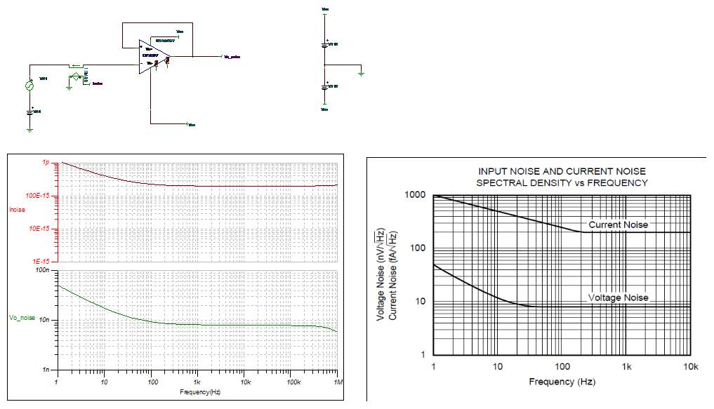
I may not make myself clearly. I used the a self-build model for simulation and its voltage and current noise density match with the datasheet. the following is simulation for this model.
you give me answer for the first question that I miss the input bias. but I have a second question. after the 2.5V biase voltage added to the first stage amp input, output noise of OP3 and OP5 matches well with my calculation. So I think there is no prpblem with my calculation and noise model of OPA2277, only the lack of input bias matches. however If lack of input bias is the problem, then why before the bias voltage added, the OP3 noise output matches calculation while OP5 noise output has a large difference from calculation? that mismatches should happen at OP3 output, too.
the attachment include simulation before and after the bias voltage added. Thank you very much.