This thread has been locked.

If you have a related question, please click the "Ask a related question" button in the top right corner. The newly created question will be automatically linked to this question.

LMC6001 response to step input

Other Parts Discussed in Thread: LMC6001, LMP7721, LMC6081

We have been trying out the LMC6001AIN in a transimpedance amplifier that uses a 100G feedback resistor. What we find is that after a current input of 0.1nA is disconnected, the output does not return to its baseline in the way we would expect. The output drops to about 50ppm of the full scale value in a time consistent with the circuit's frequency response (1.6Hz), i.e. 2 seconds, but then has a slow decay back to the baseline over many tens of seconds.

We believe we have followed good practice relevent to low currrent measurements in the design of this amplifier. We have taken heed of the article "Design femptoamperecircuits with low leakage" published in EDN by Paul Grohe.

The curious thing is if we replace a LMC6001AIN currently manufactured by Texas with a metal canned LMC6001AIH manufactured by National Semiconductor, the recovery time is much better. The output drops below 25ppm of full scale in 2 seconds. This difference is important to us and we would like to use the LMC6001AIH, but Texas doesn't make them! The difference is repeatable with several samples of ICs from different batches.

What causes this final slow decay? The negative input is at virtual ground, so it is difficult to believe it is charge storage. Also what causes the difference in behaviour between the two parts? is it the difference in package, or have other changes taken place in the design of this chip since the metal package was made obsolete?

  • Dear Bob,

    I did have the same experience with LMC6001, manufactured by TI.  I experienced even hour-long decay times.

    Before April 2012, we had still a few pieces manufactured by NS, all were in PDIP package. The by NS manufactured devices had better offset and faster return, as you have described. After April 2012 we simply couldn't purchase good functioning LMC6001's anymore. I spent over a half year trying to find a workaround, but I failed.

    Our solution was to redesign the whole circuit using LMP7721.

  • Hi Bela,

    I have tried using the LMP7721 even though it isn't really a suitable alternative in a transimpedance amplifier because of its higher input referred current noise (10fA/rootHz cf 0.13fA/rootHz for the LMC6001). Also the higher input capacitance and GBW makes it difficult to stop oscillating and achieve the same bandwidth in a sensitive transimpedance amplifier. When I tried it, I got similar dissapointing results for step recovery to the TI LMC6001.

    Note that the specs say the LMP7721 has better input referred voltage noise, but worse input referred current noise to the LMC6001.

  • Hello Bob and Bela,

    The metal can "H" package was always the best as far as leakage, but the PDIP "N" package is not far behind.

    Fresh from the rail, the PDIP and metal package leakages are nearly identical. However, the PDIP epoxy is hydroscopic and will absorb moisture over time. The metal package uses glass to seal the leads and is nearly immune to moisture (hermetic). If the DIP packages have been sitting unsealed in a humid environment for several months - then they may need to be "baked" to drive the moisture out.

    The LMC6001 die has been fab'ed in three different fabs over it's past 20 years. In 2008, National closed the Texas fab (this was well before the TI merger) and transferred the process to our UK fab. So there was a slight change in the die over the last few years. 

    The current LMC6001's are still produced in the same UK fab. They have not been transferred to TI's native fabs, so devices produced since 2008 to the present should all be the same. The package logos changed from National to Texas about a year ago (around November 2012). Other than the logo, nothing else should have changed in 2012.

    The metal can package was discontinued around 2009 - so most likely your metal can package contained the older Texas die since we built up die stock before the closure. For the same reason we discontinued the metal can package (low demand and expensive to produce), they may have sat around on your distributors shelves for a while, so you may have "old" devices even though you just got them. We would need the datecodes to confirm where and when the die came from.

    I have to ask - are you cleaning the PDIP package after each change?  It is important to flush and scrub the PDIP package - particularly UNDER the leads with clean IPA (not beer) and blow-dry with compressed air. NEVER use no-wash flux remover - it leaves a terrible residue.

    If you must handle the device, handle the device by the leads  - not the package. This is contrary to what you have been taught about ESD, but finger 'goop' between the leads attracts dust and moisture and causes leakage. A little oil on the end of the lead (away from the body) will not leak anywhere. The metal can naturally hides the "sensitive" areas underneath when handling.

    Are you using the EXACT same fixture to compare the PDIP and Metal can? Using two different fixtures introduces too many variables at these levels. Are you using a socket?

    Does the "decay" eventually settle to the same value? Or does the final value change after each event?

    While it is true the non-inverting input is at "Virtual" ground, it is being held there by some very high impedances (100Gohm). It is very easy to externally influence this node - with both intentional an UN-intentional devices (stray caps with uncontrolled dielectrics).

    As for the LMP7721 - the current noise is higher because of the active guard-driven ESD diodes. Amplifier noise gets into these diodes and "modulates" them - so there is a bit more current noise due to the active guarding.

    Because the 7721 is a low-noise device,  the input stage has more gate area - so the input capacitance is much larger (11pF) than the 6001 (<3pF). You will need a (small) compensation capacitor across the feedback resistor to prevent peaking and stability issues (oscillations) when using the LMP7721.

    Regards,

  • Hi Paul,

    Thank you for your knowledgeable and informative response. You have certainly answered some of our questions, but I don't think everything is resolved

    All AIH the devices we have managed to get hold of have the code "H9910" on them.

    Incidently, the AIN devices we have used have differing codes. Apart from the data code, some are prefixed "JR" and some are prefixed "KR". Although I can't say that it makes any difference to our decay problem, the KR parts seem to have a higher input bias current. What is the significance of this letter?

    Yes we clean (IPA in an ultrasonic bath) and we "bake" the completed boards (but only at 50C for 20 minutes) . Perhaps it needs to be baked at a more elevated temperature. Can you suggest a time and temperature that would be needed to bake these parts before their performance approached that of the AIH parts?

    Yes we are using exactly the same fixtures to test. No we don't use a socket. Pin 2 is in the air.

    The decay always settles to the same value within a reasonable margin of error (i.e. allowing for base-line drift over time) One thing I didn't mention is that the level this slow final decay kicks in at depends on how long the input current has been applied. The metal canned devices are much less sensitive to the time that the current has been applied.

    Even accepting your explanation of leakage as the cause of this slow decay, I am still mystified as to how it causes such a  long time-scale phenomenon. I have tried modelling it and introducing various flaws into the circuit, but nothing seems to generate the behaviour we see.

    The LMC6001 data sheet says "By tightly controlling the molding compound, National (or Texas) is able to offer this ultra-low input current in a lower cost molded package" That's not the sort of thing you see in every data sheet and implies that there is something special about the molding compound used for this particular device. Is this true? Also, have there been any changes in the molding compound over recent years,?

  • Hi Bob,

    Those cans are 14 years old...from 1999. A lot has happened since then.

    The LMC6001 die was probably fab'ed in the UK fab - same place the new devices are fab'ed - but there may have been changes in the fab since 1999. The guy with all the answers is out today, so we can find out more on Monday. But it looks like things have been fairly stable for the last 10 years or so, as far as the die goes.

    There was a mold compound change to "Halogen Free" compound in early 2009 for the PDIP packages.

    We will need to know the exact package markings in order to trace down the lot/fab/date information. The new codes are not really human-readable and require a secret decoder ring. There may be fab/lot information on the label on the box or ESD bag the rails came in.  Look for a "LOT: XXXXXXXXXXXXXXX'  over a bar code on the label.

    50°C is a good temp, but you may want to bake a little longer, maybe an hour (make sure all the components can handle that - particularly plastic mechanical devices.

    You can also bake the DIP packages separately before mounting - if they have been exposed to moisture.

    However, a resistive leakage would cause the overall settling time to increase or decrease (depending on the polarity), and then a constant offset in the baseline.

    What you are describing almost sounds like capacitive soakage (or capacitor "memory effect"), especially when you mention that the decay time is proportional to how long the input current was applied.

    See page 304 of the "Pease Hompeage" PDF for a description of capacitive soakage:

     What's All This Homepage Stuff, Anyhow?

    Also see page 41 and 44 about the story of femtoamps - especially the part about his smart technician Paul...:^). It was inspired by how to create a fixture to test the LMC6001 in production reliably to 20fA.

    Again, we will need the full datacodes and any markings on the devices. The Lot code off the packaging is even more useful. If you got them through Digikey or our other primary distributors, it may be listed on their label.

    Regards,

  • Dear Paul,

    Mr Pease (and his golden-handed technician called also Paul :-) ) has produced really great things, and, which is also very important, he could write great, enjoyable articles. I like his kind of humour.

    To the theme LMC6001: maybe you can remember, about a year ago we discussed a lot about a femtoampere-sensor. It was an LMC6001 in transimpedance configuration, fed back by 1 teraohm.

    In that project I spent roughly a half year, trying to detect, why our sensor got so bad. The phenomen is very similar to that of Bob's: after applying an input signal, the time it requires to return to zero is extremely long. Interestingly, the step-up time got also longer, but not proportionally, it is faster then the step down.

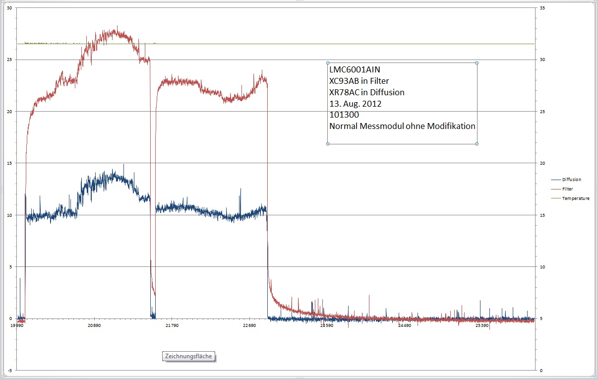
    I found an old file of comparison. I just insert two pictures here because the original excel is almost 20 Mbyte.Y axis is in femtoamperes, X axis is scaled in seconds. The two pictures are displaying the same measurement, I just zoomed to the On - Off part.

    Here you can see an "old" (blue curve) and a "new" (red curve) LMC6001. Our sensor has two parts, they're exactly the same except the sensor itself. In this test we took the sensor module, gave him a gas through, and recorded the output signal.

    The difference of the signal amplitudes is absolutely normal, just look at the zero signal (Uoffset+Ibias*Rfeedback), the rising and the falling edge behaviour. Believe me or not, when we had two "old" LMC6001s, both edges were sharp, like the blue curve on the pictures. When we replaced the "filter" sensor to a newer LMC, we experienced this slow settling.

    We had the same experience with date code JR05ABE3, KR18ACE3, XR78AC as well.

    When the IC was soldered into the circuit, I always cleaned them carefully with ethanol (we have here a lot). I also tried other cleaning agents without difference. Baking on 50°C for an hour is standard. (I also tried to sacrifice a black doodle-doo at full moon in a ring of virgins, having a black cat on my collar, but it didn't help)

    Since I created the same circuit by LMP7721, it works fine again.

    I do hope, this info is helpful and you can find something to improve the LMC6001 back to it's original quality.

  • Sorry, XR78AC is a date code for the good "old" LMC6001.

  • Hi Paul,

    Thanks for the batch code comments, but I think I'll leave the plastic part batch codes alone for now. Until I can get any of the plastic parts working satisfactorily, it is little more than an interesting diversion.

    Let me say that I have always been a big fan of the writings of Bob Pease and I am familiar with the articles you mention. One of my favourite Pease sayings goes something like "In theory there is no difference between theory and practice, but in practice there often is".  This seems to be one of those cases. I would like to try and narrow the gap.

    I agree that the phenomenon looks a lot like dielectric absorption, in fact that was what it was thought to be initially; dielectric absorption in the cap in parallel with the feedback resistor. However it can't be that because when everything else is right (board layout, capacitor & resistor handling and selection) the magnitude of the problem is mainly determined by the chip we use. While I accept that a node at 100G (or 1T) from ground is going to be highluy susceptible, I want to understand exactly how it is being affected so I can do my best to eliminate the effect if possible.

    I accept what you say that the encapsulant absorbs water, but as I mentioned before, I am not sure I see why leakage through the encapsulant would cause the problem we see. I might expect it to cause an offset (current from the rails finding its way into pin 2), but that ought to be constant. Pin2 itsef is at "virtual ground, which of course is not exactly at ground. We have the input offset voltage of 1.35mV max. That will be the potential driving current from pin 2 to ground, which will be constant. We also have a not inconsiderable capacitance to ground on this pin because of the external circuitry it is connected to (~200pF). but since the input offset should be pretty much constant, this also should not affect the pulse response.

    Then there is the question of the effect of the Op-Amp's finite gain. Our circuit has an output on pin 6 of a few volts, say -3V at full scale current. This means that the input will have a voltage of  3/Av = 10uV below the input offset voltage. When the current stops, this will have to go to zero. Leakage through the package will not cause this change to be delayed. You intuitively might think that the external capacitance holding this 10uV would cause a delay in the step change,but in fact it doesn't  make a noticeable difference, as disconnecting the external circuitry demonstrates. In any case, if this was the problem, I would expect the step response to be slow from the sword go, not to go quickly down to 50ppm of the maximum value and then start behaving slow.

    So following Mr Holmes's maxim that once having eliminated the probable, we must contemplate the possible. How about if the problem really is due to dielectric absorbtion, but it is due to dielectric absorbtion within the chip encapsulant? That would qualitatively give an explanation even though it is difficult to credit that it would quantitively. The incoming current pulse gives rise to a (massive) 10uV shift on pin 2. The electric field between this and the nearby grounded pins slowly polarises the epoxy. When the current stops, the polarisation is slowly removed and produces a current into pin 2. This would explain why we (and Bela) have had so little success in baking our chips to get rid of moisture. It would also explain why the metal canned devices performed so much better. (see AVX's data on low dielectric absorption on their ridiculously expensive glass capacitors).

    Bottom line Paul, do you have any figures for

    a) the inter-pin capacitance on the 8 pin DIP package used by the LMC6001 (excluding the on-die capacitance that is).

    b) the dielectric absorption of the molding material.

    If we had those figures, we could calculate the theoretical magnitude of this effect. If it tied in with what we are seeing, we would at least know what the cause of the problem was, even if we did not have a solution.

  • Hi Bela & Bob,

    Hmm...Bela,  I see what you mean....I believe you!

    How are you resetting?? What is the "shorting" resistance? Are you shorting the feedback resistor or disconnecting the input? I'm trying to establish what the impedance would be at the input during the "decay" time.

    As an experiment, try using a LMC6081and see what happens. The LMC6001 is based off the LMC6081 (basically the same device except for some minor tweaks). See if you get the same decay signature. This would tell us if it is an issue specific to the LMC6001, or to the process.

    Bob,

    I have seen "dirty" packages leak in strange ways before - so it is a standard question to make sure that the packages/circuit are being cleaned and baked. It is part of the "20 questions" I have to ask...Bela is cleaning and baking, so that does not seem to be the issue.

    I agree with you. I do not believe it is moisture at this point. It has something to do with the die or the mold compound. Those are the only logical things that have changed in the circuit.

    The biggest changes to the 6001 occurred in 2008, when the fab was transferred to UK and the mold compound was changed to halogen free to meet RoHS requirements. So any step-changes should have happened back then. It is possible that it took a few years for the devices to make it to you. $10 specialty op-amps are not a high volume business, so getting parts a few years old is not uncommon (and again, why I was concerned about moisture).

    If you could, please provide us with the date codes of LMC6001's you considered "good" and "bad'. This can help us narrow down the period when changes may have occurred.

    Also - I will be going on an extended holiday starting Wednesday , and will not be back until Jan 6th - so please do not think I am ignoring you if I don't replay after Tuesday evening...

    Regards,

  • Hallo Paul,

    > How are you resetting?
    I do not reset anything. And, before you ask, there's no feedback capacitance as well, except the stray capacitance.
    Resetting is a great idea, if you could offer me a switch, what can be paralelled with a 1TOhm resistor, I'm really interested in. I couldn't find any, which has an isolation resistance specified high enough and doesn't injecz charge into the summing point. Of course: measuring 1TOhm takes about a quarter of an hour, even with our Keithley sourcemeter.

    > Are you shorting the feedback resistor or disconnecting the input?
    Neither. Our system measures nanoparticles in a gas flow. Zero input signal means: I turn the gas flow off, together with the bult-in gas-ionisator. In this case the output of the amplifier is considered as offset, and once in an hour it is stored for later calculation purposes. What you see on the excel sheets above is a special case, I let the instrument run for 3 days long, and I turned the gas flow on and off a few times. It was a good practice to check the long term stability of the amplifier - it is OK, but the rising and especially the falling of the output is not acceptable.

    The sensor plates are glued into the PCB, they reside in a special plastic holder. It's material is so good isolator like quarz glass. This part doesn't change, I tested only the amplifier IC. The whole sensor is in a shielded case.

    > As an experiment, try using a LMC6081and see what happens.
    Also good idea, I would do it gladly, but ... our problem is solved by LMP7721, therefore I got new projects to work on. They are also urgent, I couldn't manage the time and the PCB (I made another, it isn't suitable for LMC6001) to make such a test.
    To organize the necessary goods and time, it could take more months. If I don't forget it :-)

    Next week I also go to holiday and I'll be back on 6th of January.

    I wish you merry christmas, happy new year and a lot of fun!

  • Hi Bela,

    They do make switches capable of fA performance  - they are called reed relays. But not just *any* reed relay.

    CMOS or JFET switches or Muxes are not suitable for the reasons you mentioned because of capacitive charge injection and junction leakages.

    The big boys like Keithley and HP have been using reeds since their beginnings. Because it is magnetically operated, the reed tube can be enclosed within a copper guard - guarding it from the "outside" world.

    Reed relays are fully capable of  "resetting" functions - as they are truly "floating". But there are some tricks to reduce the jumps - having to do with the speed of the voltage going into the coil. If you can control the coil ramp rate, you can control the "jump".

    The reed forms a one-turn step-down transformer with the coil (A 5V coil is about 3K turns). For the period between when the coil is first energized until the time the reed opens, a small voltage is induced across the contacts.  When the reed opens, it "breaks" the turn and any capacitance in parallel with the reeds will then remain at that voltage (like a sample/hold).

    While that voltage may go unnoticed in most applications, in the Femtoamp world, that is more than enough to cause a big jump. The goal is to minimize that induced voltage by controlling the coil dv/dt.

    Most relays are driven with a full on or off voltage (5V, 12V or 24V) by a single transistor, which creates a large dv/dt across the coil. Transformers also have a lower frequency limit, which comes in handy.

    If you slowly ramp the coil voltage down through the release voltage range, you can minimize the jumps considerably. This was the "trick" I developed (and is mentioned in the Pease article) to reduce the reset jumps on our integrator after I noticed the "jumps" were proportional to the coil supply voltage and/or how fast I ramped the supply to the relay coil.

    For the 12V Coto relay we used, there was a small window where the relay would release (AKA the "drop out" voltage). So instead of going full 12V to 0V to open the relay, we went slowly between, say 6.3V and 6.2V (Don't remember the exact voltages - but it was well below 12V). At this point, the jumps are much, much smaller, manageable and predictable. With a steady hand, I could slowly drop the coil voltage and open the relay slow enough to cause a jump of only a few percent.

    The drawback, of course, is timing. There will be a variance in the release time  - so not good for fast sampling or synchronizing - but nothing moves fast in the fA range. You also will need to "calibrate" each relay individually for the dropout voltage since they will vary device to device.

    Of course, you don't need a coil surrounding the reed. If you look inside Keithley's high end electrometer - the reed switches are actuated by a magnet on the end of a metal rod. Beautiful stuff...

    There are several manufactures of reed relays. Sanyu, Coto and Meder make the low-current stuff. The best ones are the "open frame" ones where the ends of glass tube is visible sticking out of the coil (usually within a copper tube) - so you can connect directly to the reed - like the Sanyu 90 series.

    I'm glad you are happy with the LMP7721...and at half the price!

    Regards,

  • Paul,

    There are no PDIP LMC6001AIN devices that we consider good enough for our PCB design. The only ones we have seen that are good enough are the metal canned ones I already gave you the code for.

    I think that I will have to say that you have answered my original question as well as you are able, so I am going to try and mark it as answered. Although it has not come up with a proposal for how to fix the problem, this discussion has given me a few ideas I will go away and pursue. So thanks for your time and input and have a happy Christmas break.