This thread has been locked.

If you have a related question, please click the "Ask a related question" button in the top right corner. The newly created question will be automatically linked to this question.

Measuring high side current on negative rail with INA138 - How to ?

Other Parts Discussed in Thread: INA138, INA226, ISO1540

Hi all

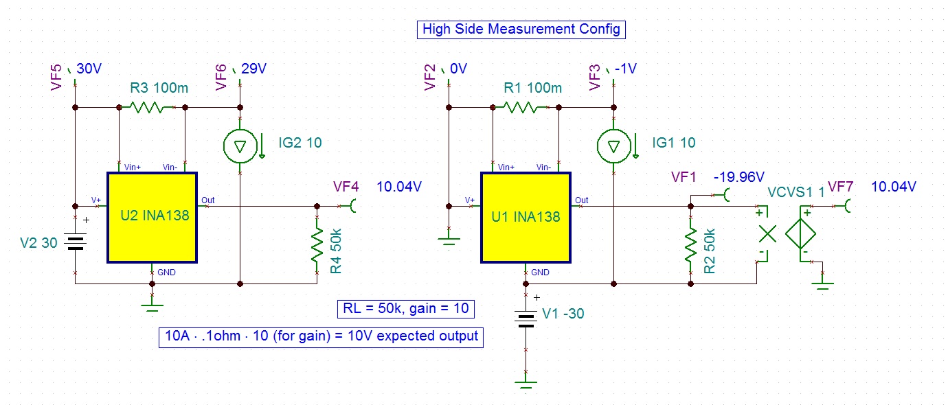
I want to measure the current across a 0.1ohm resistor on a -30V rail with INA138 and read a 100mV/A drop across the resistor. Is this the proper way to connect ? or should the V+ and GND terminals be connected in the normal way ? 
From the TINA screenshot, this is not the output voltage i was expecting on the negative rail...
Thanks and regards

Soumitra 

Im

  • Soumitra,

    I did a little playing around with your circuit in TINA and I expect I have a little different result from your circuit analysis, see my schematic below

    More to the point though, the INA138 is a high-side current shunt monitor and I believe this is a low-side measurement you are trying to make.  While 30V supply and common mode is within the 2.7 to 36V range, measuring on the low end is not the intended use of this device.  I did a little High Side config and found it to work but I don't know that it will suit your application since the current draw is reversed.

    I went looking through our catalog and I don't see anything that is a drop in fit for your circuit exactly as presented (mostly because of the 30V supply) but perhaps if we knew a little more about your application we could find something that will work for you.  If you could share a little more about what you're after, we will certainly do our best to assist you.

    Thanks!
    - Jason Bridgmon

  • Hi Jason

    Thank you for your reply. Unfortunately I could not see any of your attached schematic images in three different browsers, could you kindly attach them again please ?

    My application is for a dual rail power supply and yes these are for high-side shunt monitoring. What got clipped out in my schematic is the rest of the regulator etc and load on the right side of the image.

    Regards

    Soumitra

  • Soumitra,

    The second image is attached, the first one is less relevant.  I show here how to hook up the INA138 to get it to work for a high-side measurement.

    I am using the current shunt monitor selection page: http://www.ti.com/lsds/ti/amplifiers-linear/current-shunt-monitor-products.page to look for suitable CSMs for your application.

    A little more complex solution is to use an I2C output low-side CSM, powered using a Zener Diode structure between the ground and negative supply lines, and then use an I2C isolator to upconvert the voltage for the I2C bus to something manageable.  For this I would look into using a product like the INA226 http://www.ti.com/lit/ds/symlink/ina226.pdf and an I2C isolator like the ISO1540 http://www.ti.com/lit/ds/symlink/iso1540.pdf.

    I hope this helps!

    Jason Bridgmon

  • Hi Jason

    Thank you for  your inputs. I think the second schematic just about solves the issue but I really wanted to use the the components i had at hand without increasing the BOM. Could you tell me a little more about the VC-Voltage Source configuration you used in your schematic ? 

    Thanks and regards

    Soumitra

  • sorry, the voltage controlled voltage source is a mathematical construct in tina used for simulations, it isn't a real device you can put on a board. Jason Bridgmon
  • Yes Jason im aware of that but there are real-world devices (well constructing them out of opamps etc) simulating the VCVS as well. Just increases the component count though.

    Regards

    Soumitra