This thread has been locked.

If you have a related question, please click the "Ask a related question" button in the top right corner. The newly created question will be automatically linked to this question.

photo diode amplifier

Other Parts Discussed in Thread: OPA140

dears all,

somebody please ans my questions

1.in some AC coupled photo diode Amplifiers there used to be one resistor between the AC coupled capacitor and 

inverting terminal of op-amp, what is the advantage of this resistor.

2. on what all factors junction capacitor of photo diode effects.

3. how to calculate feedback capacitor (Cf) with respect to OPA140 and on what all factors it depends.

4. circuit is oscillating when the feedback resistor of second stage is increased to first stage feedback resistor..

5. required frequency range of the circuit is 8Khz to 25KHz and each stage gain required is 50.

 please somebody guide me in detail
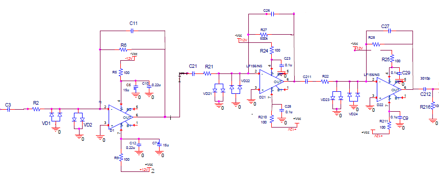
thank you.

suresh bagewadi

  • Suresh,

    I'll do my best to answer your questions:

    1. The input resistor determines the input impedance of the amplifier, this creates a high-pass filter with the input capacitor to limit the low frequency signals.

    2. The junction capacitance of the photodiode is a main consideration for the stability of the amplifier. Any capacitance to ground from the inverting input creates a zero in the 1/B curve of the amplifier, which degrades the phase margin. If this is not corrected before the 1/B intersects the open loop gain curve, the amplifier will be unstable. An excellent description of this can be found here: http://www.ti.com/lit/an/sboa055a/sboa055a.pdf . Remember that this effect is the result of all capacitance to ground from the inverting node, which includes the photodiode capacitance, protection diode capacitance (VD1, VD2, etc.) and amplifier input common-mode capacitance. This zero in the 1/B curve will also increase the noise of the amplifier above the zero frequency.

    3. See the above mentioned app note.

    4. The feedback resistor value must be considered when calculating the feedback capacitor C26, therefore resistor R27 cannot be increased without changing C26 as well. 

    5. A gain of 50 is extremely low for photodiode applications and could be accomplished in a single stage, why are additional amplifiers being used?