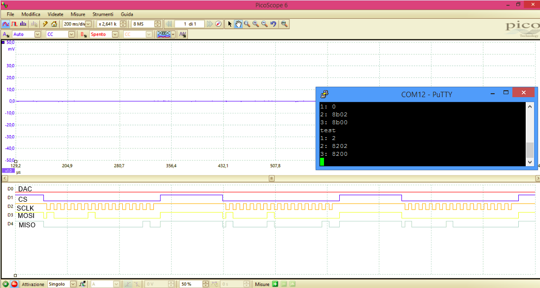
Other Parts Discussed in Thread: AFE031
hi, i'm trying to comunicate with an AFE031, i would like to understand how receive data from the spi, if i need a cycle of reading after one of sending data.
here is the code i wrote:
#include "inc/hw_types.h"
#include "inc/hw_gpio.h"
#include "inc/hw_ints.h"
#include "inc/hw_memmap.h"
#include "driverlib/sysctl.h"
#include "driverlib/interrupt.h"
#include "driverlib/rom_map.h"
#include "driverlib/gpio.h"
#include "driverlib/timer.h"
#include "driverlib/ssi.h"
#include "driverlib/pin_map.h"

#include "utils/uartstdio.h"
#include "driverlib/uart.h"

#define PINDAC GPIO_PORTA_BASE,GPIO_PIN_6

unsigned long DataRx[1];


void ConfigureUART(void);

int main(void) {


	SysCtlClockSet(
			SYSCTL_SYSDIV_5 | SYSCTL_USE_PLL | SYSCTL_XTAL_16MHZ
					| SYSCTL_OSC_MAIN); 						// Clock setting

	MAP_SysCtlPeripheralEnable(SYSCTL_PERIPH_GPIOA); 		//Abilita la porta A
	MAP_SysCtlPeripheralEnable(SYSCTL_PERIPH_GPIOF);
	SysCtlPeripheralEnable(SYSCTL_PERIPH_SSI0); 	//Abilita periferica SSI0

	ConfigureUART();

	GPIOPinConfigure(GPIO_PA4_SSI0RX);
	GPIOPinTypeSSI(GPIO_PORTA_BASE, GPIO_PIN_4);

	GPIOPinConfigure(GPIO_PA3_SSI0FSS);
	GPIOPinTypeSSI(GPIO_PORTA_BASE, GPIO_PIN_3);

	GPIOPinConfigure(GPIO_PA2_SSI0CLK);
	GPIOPinTypeSSI(GPIO_PORTA_BASE, GPIO_PIN_2);

	GPIOPinConfigure(GPIO_PA5_SSI0TX);
	GPIOPinTypeSSI(GPIO_PORTA_BASE, GPIO_PIN_5);


	SSIConfigSetExpClk(SSI0_BASE, SysCtlClockGet(), SSI_FRF_MOTO_MODE_0,
			SSI_MODE_MASTER, 10000, 16);
	SSIEnable(SSI0_BASE);


	GPIOPinTypeGPIOOutput(PINDAC);

	unsigned long rxdata;

	UARTprintf("test\n");

	SSIDataPut(SSI0_BASE, 0x8200);
	SysCtlDelay(13333);
	SSIDataGet(SSI0_BASE, &DataRx[0]);
	SSIDataPut(SSI0_BASE, 0x0000);
	SSIDataGet(SSI0_BASE, &DataRx[0]);
	while (SSIBusy(SSI0_BASE))
		;
	UARTprintf("DieRev: %X\n", DataRx[0]);

//	SSIDataPut(SSI0_BASE, 0x8A00);
//	while (SSIBusy(SSI0_BASE))
//		;
//	SSIDataGet(SSI0_BASE, &DataRx[0]);
//	UARTprintf("DieRev: %X\n", DataRx[0]);

	while (1) {

	}

}


void ConfigureUART(void) {
	//
	// Enable the GPIO Peripheral used by the UART.
	//
	SysCtlPeripheralEnable(SYSCTL_PERIPH_GPIOA);

	//
	// Enable UART0
	//
	SysCtlPeripheralEnable(SYSCTL_PERIPH_UART0);

	//
	// Configure GPIO Pins for UART mode.
	//
	GPIOPinConfigure(GPIO_PA0_U0RX);
	GPIOPinConfigure(GPIO_PA1_U0TX);
	GPIOPinTypeUART(GPIO_PORTA_BASE, GPIO_PIN_0 | GPIO_PIN_1);

	//
	// Use the internal 16MHz oscillator as the UART clock source.
	//
	UARTClockSourceSet(UART0_BASE, UART_CLOCK_PIOSC);

	//
	// Initialize the UART for console I/O.
	//
	UARTStdioConfig(0, 115200, 16000000);
	//
	UARTStdioConfig(0, 115200, 16000000);
}
thanks