This thread has been locked.

If you have a related question, please click the "Ask a related question" button in the top right corner. The newly created question will be automatically linked to this question.

TLC2272 differentiator unexpected result

Other Parts Discussed in Thread: TLC2272

Hello,


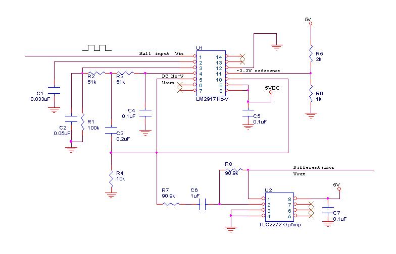
I'm having an issue with a differentiator implementation of the TLC2272 receiving an input from a LM2917.  The application is a BLDC motor halls square wave input to the LM2917, which then outputs a corresponding analog value to a differentiator to monitor acceleration.


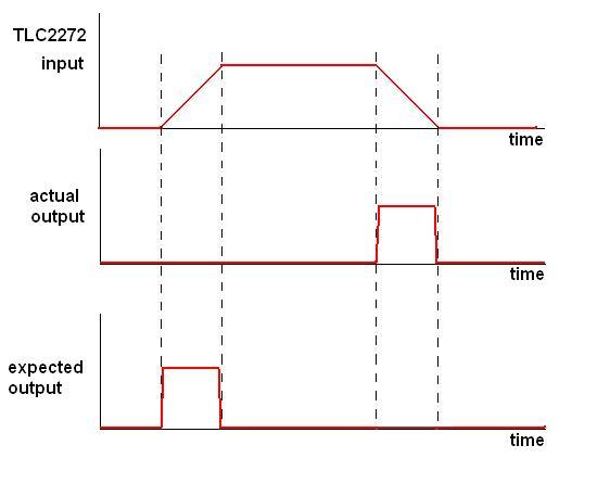
My problem is that the expected differentiator output is reversed: An increasing input gives no response, and a decreasing input gives a positive response.  Setting my non-inverting input to 1/2 Vdd shows the increasing input gives a negative response, the opposite of what I expect. 
  • Hi Giuliano,

    The TLC2272 connected as shown is an inverting differentiator that uses a single, +5 V supply. It has a voltage output: 

    Vo = -R8 C6 (dVin / dt)

    There is an inversion at the output. Since the output cannot be driven below ground it stays near that level when a positive dVin /dt occurs. It moves positive when dVin /dt is negative. That coincides with the result you are obtaining.

    Regards, Thomas

    PA - Linear Applications Engineering

  • Thank you for your time, Thomas.  I was not aware of the negative in that equation (and at the least I can rest knowing that I'm not insane for getting such a result).

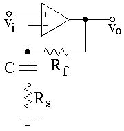
    So, I found a non-inverting circuit online (below) but unfortunately, while the output is proportional, my differentiator output is now just mirroring the input (stays high even after the input is no longer increasing). Any insight?

  • Hi Giuliano,

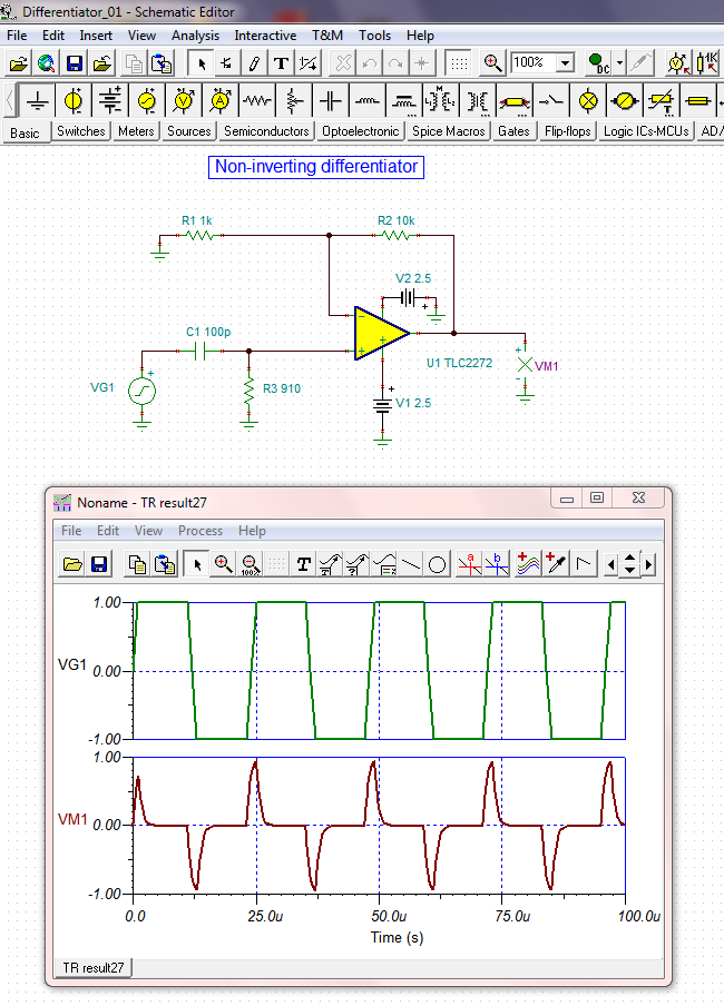
    There are several topologies for a simple, non-inverting differentiator. They reduce to a non-inverting amplifier with a gain of RF/RS at higher frequencies where the capacitive reactance is very small. A non-inverting differentiator that I've evaluated is very similar to the circuit you had drawn. Its circuit is seen below. The R and C values have been picked such that a 41.7 kHz square-wave, having a 1 V/us edge rate, results in the positive and negative going "blips" associated with a differentiator. Note that the blips have the same polarity as the input waveform edges.

    The R and C values could be selected to differentiate the input waveform as needed. A dual polarity supply is necessary if the output must swing below ground.

    I have attached the TINA Spice circuit simulation file should you want to try simulating it.

    Regards, Thomas

    PA - Linear Applications Engineering

    Differentiator_01.TSC