This thread has been locked.

If you have a related question, please click the "Ask a related question" button in the top right corner. The newly created question will be automatically linked to this question.

Thermal transient behavior of INAs and OPAs

Other Parts Discussed in Thread: INA331, TINA-TI

Hi,


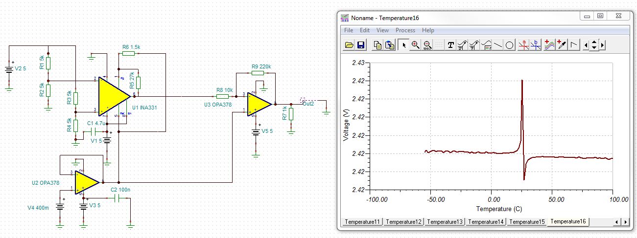
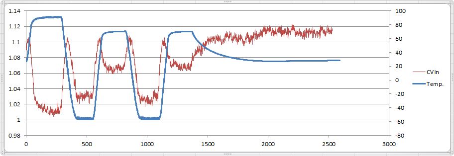
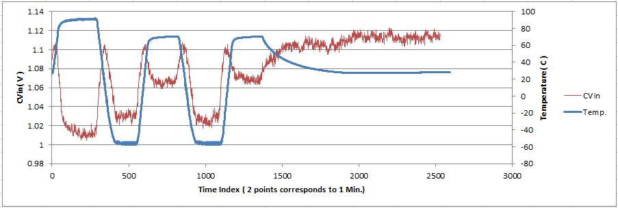
May I know more info. on thermal transient behavior of  INAs & OPAs (specifically INA331). Because in one of our amplifiers we experience higher overshoots of the output during the temperature transients of about  2 o C/Min    before it becomes stable after the transition time.

Thanks in advance,

Kavindu

  • Package defect; bond wire lifting off the pad, delamination of the die, poor tempco of passives around the circuit, bad solder joints....

    This needs a circuit and a more detailed description of the application. Is this a DC circuit that exhibits an unsuspected increase in output voltage during heating or is this AC phenomena indicative of poor phase margin? So what are you measuring and how are you measuring it?

    -Ken

  • Kavindu,

    Overshoot in INA's and op amps is closely related to the phase margin (see below), which in turn is a function of the bandwidth: BW=gm/Cc=Itail/(Vt*Cc) where current in the input stage, Itail~IQ, and Cc is a Miller compensation cap.

    If IQ increases with temperature, as is the case in INA331 (see below), it causes the increase of the bandwidth and thus a lower phase margin which translates into a higher overshoot.

    However, 2 deg C temperature change you allude to should make no significant difference in the overshoot UNLESS your design is marginally stable to start with. For that reason, all PCB applications should be designed with no more than 25% overshoot (or minimum 40 deg phase margin) in order to assure stable operation over the wafer process and temperature variations,  Also, make sure to have decoupling caps between the voltage supplies installed right at the pins (minimum 0.1uF).

  • Thank you for your comments, Still I'm not clear. So I added more info. into the thread.

     Following is a TINA-TI simulation for the circuit I'm testing.  All resistors are 25 ppm.

    The real test data measured at the output is shown below

    As can be seen there are over shoots during temperature variations. 

    Can you please comment on why we see these over shoots

    Best Regards,

    Kavindu

    amp-1.TSC
  • What are the axes and scale?

    -Ken

  • Ken,

    pls see the corrected plot

    VBR,

    Kavindu

  • Kavindu,

    I am not clear what the CVin vertical axis on your graph show - there is no such label on your schematic (see below) and with the componets values you use there is no node with potential around ~1.06V - see below.

    Other than that, the recommended resistor values for gain of 95 you use should be R5=180k and R6=10k, G=5+5*(180k/10k)=95, and NOT 27k and 1.5k, respectively, as shown on your schematic - see below.

  • Thank you all for your attention on this regards and sorry if I'm keep on confusing you. 

    Actually the CVin corresponds to the out2 of the schematic and the front end of the INA is fed by a Strain gauge bridge in real. I just put 4 resistors to represent those so that the value at the CVin  may  have different simulated values opposed  to real values depending on the bridge balance.

    Best Regards,

    Kavindu

  • Hi, If anyone can give some heads-up on this regards it'd be a great help

    Thanks,

    Kavindu

  • Kavindu,

    You need to be much more specific about the issue - asking an open-ended question like what is the thermal transient behavior of INAs and op amps is much too broad.  In general, there should be only small variations in transient behavior as compare to room temperature BUT with this type of questions the devil is typically in details.  I previously pointed out that the INA331 recommended resistor values for gain of 95 you use in your application are R5=180k and R6=10k, G=5+5*(180k/10k)=95, and NOT 27k and 1.5k, respectively, as shown on your schematic.  Have you tried these values as the current drive of INA331 may be unable to drive 1.5k load.

    If you need further assistance, please provide detailed application schematic with actual values of components used.