This thread has been locked.

If you have a related question, please click the "Ask a related question" button in the top right corner. The newly created question will be automatically linked to this question.

Inaccurate output for differential amplifier

Other Parts Discussed in Thread: OPA333, INA333

Hi, I am building a potentiostat circuit and a part of the circuit is to compare the output with initial input to produce a feedback to the cell. 

The initial input is output of DAC with ramp form, range from 1.2V to 3.8V but it's referenced at 2.5V. The output of the cell is around that range so I want to implement this process in two steps:

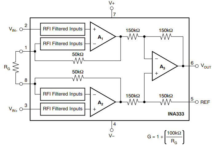
- pre- process the output signal with an Ins Amp 

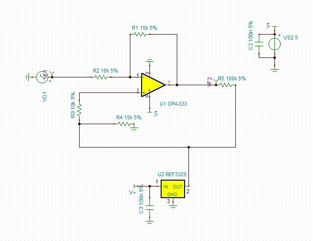
- Send the it through a differential amplifier with the other input is the initial DAC signal

So, I have two questions: 

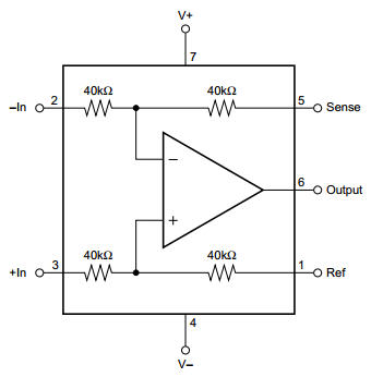
- Is there any Ins Amp with gain = 1 so I could take the voltage drop out of the cell or could you suggest me any better way to deal with this?

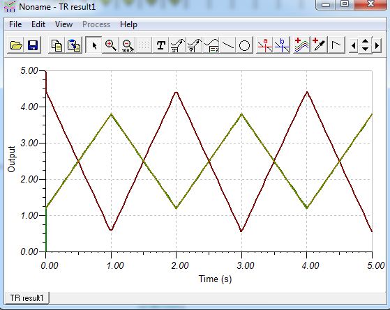
- I have simulated the differential amplifier with TINA but it produced inaccurate results. Here is my simulation, could you take a look and give me some advices?

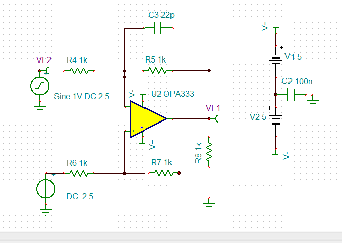
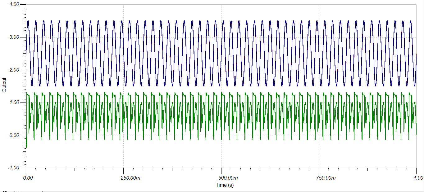
The green one ís VF1 signal, I think that the result should be a sine wave with Vpp = 1V because I just subtract the DC level from the sine signal.

Regards, 

Quan

  • Quote,

    OPA333 maximum specified supply voltage is 5.5V (or +/-2.75V) but you operate the part on +/-5V supplies (10V total).  Your power supplies are not only above specified limit but also above Absolute Maximum Rated supply voltage of 7V that may result in damaging the part (see below).

  • Thanks for your reply, I corrected my simulation circuit as you said. Besides, it seems that op amp can't handle DC signal, I change all the source to voltage generator and it worked as I expected :)

    One more question, as I mentioned above, is there any Ins Amp with gain equal 1 for pre-processing or should I just put a buffer instead?

  • Hello Quan,

    Most of our instrumentation amplifiers can be set to a gain of 1V/V by not populating the gain-setting resistor. Please refer to the INA333 block diagram and gain equation below.

  • Thank you, I will try it out :)

  • It's me again :D This time I have a differential amplifier with reference, it's attached below.

    The green one is VF1 and the purple one is VF2. It produced the result I want, inverting and amplified by 1.5.  In my real circuit, both the ref 3225 and VG1 are replaced with micro-controller DAC. However, it produced different result:

    As you can see, the circuit produced the absolute value of input. When the input is lower than the reference, it's flipped to the other side but I want it to be similar to simulation result. Could you give me any advice?

    Thank you in advance!

  • Hello Quan,

    Despite your simulation results, the output of the amplifier is connected to the reference voltage and cannot pull the output below 2.5V.  

    Below is the general schematic for a difference amplifier.  Notice where the reference voltage is applied.

    In the schematic above pins 5 and 6 should be shorted together in order to provide negative feedback for the amplifier.  The reference voltage should be connected only to pin 1.

    I hope this helps.

  • Hi Pete, Thank you for your help, as you suggested I connect both the reference pin and V- input pin to the reference, the V+ input pin to the input signal and my desired result is acquired :D