This thread has been locked.

If you have a related question, please click the "Ask a related question" button in the top right corner. The newly created question will be automatically linked to this question.

Trouble with OPA357 enable/disable

Other Parts Discussed in Thread: OPA357

I would really appreciate a little guidance in using the OPA357 as a transimpedance amp.  I am using the following circuit as per the data sheet (except Rf = 500 KΩ, not 10 MΩ):

I am using the following photodiode: http://www.thorlabs.us/thorcat/0600/FDS100-SpecSheet.pdf, which has a 24 pF capacitance.  

When I try to drive the enable/disable with a 0V low / 5V high square wave, I get the following output on my scope:
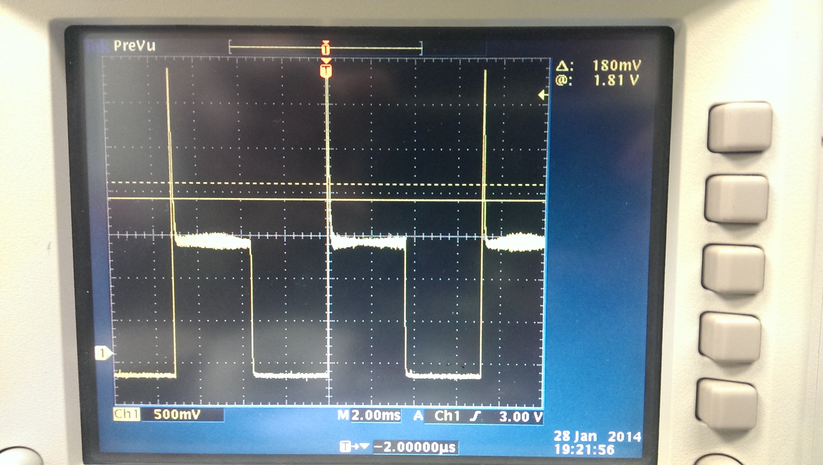
I am getting a very large spike (gain peaking?) at the start of each enable cycle which takes a few hundred microseconds to settle.  This is a large problem for me since I would ideally like to measure from the amp about 1-5 microseconds after enabling.  Is this typical behavior for the OPA357?  I thought not since the data sheet says the enable time is ~100 ns.  

Thank you very much for any assistance.

  • Hi Sean,

    When I simulate your OPA357 circuit in TINA Spice it predicts the high level transient when the amplifier is enabled and a continuous photodiode current is present. This is likely caused by charge transfer when the system is perturbed going from being turned off, biasing up, and then the on condition. Dc levels change tremendously and the output goes from a very high impedance state to a very low impedance state during the event. The fact that the simulation predicts this behavior tends to support charge transfer hypothesis.

    I looked for a way that one might reduce, or clamp, the transient. One idea that works in simulation is adding a very low leakage diode across the feedback resistor; the anode connected to the inverting input, the cathode to the output. When I run a transient analysis the transient disappears.

    If this works in the real circuit it may be a solution providing that the diode doesn't add too much capacitance, or leakage current. Otherwise, the transimpedance amplifier bandwidth and dc performances could be compromised. A 1N4148 fast switching diode was used for the simulation, but an even lower leakage, lower capacitance diode would be best. You may want to try adding a diode to your circuit and see if it makes any difference.

    The enable/shutdown feature included with operational amplifiers is primarily intended to add power down capability - to save current when the amplifier is not in use. Other electrical performances of the amplifier that may occur as the result of employing the function are often not characterized, or stated. I do expect that this turn-on behavior will occur with many operational-amplifiers having an enable/shutdown capability.

    Regards, Thomas

    PA - Linear Applications Engineering   

  • Hi Thomas, 

    Thank you very much for your response.  I will try to get my hands on a low leakage, low capacitance diode and connect it as you suggested.  I'll get back to you with the results as soon as possible.

    Thanks again for your help

  • Hi Thomas, 

    Thank you once again for your help with my issue.  As you suggested, I placed a fast switch diode across the feedback resistor in the circuit.  I didn't have anything better than the 1N4148 you used in your simulation, so that had to do.  The resulting circuit looks like this:

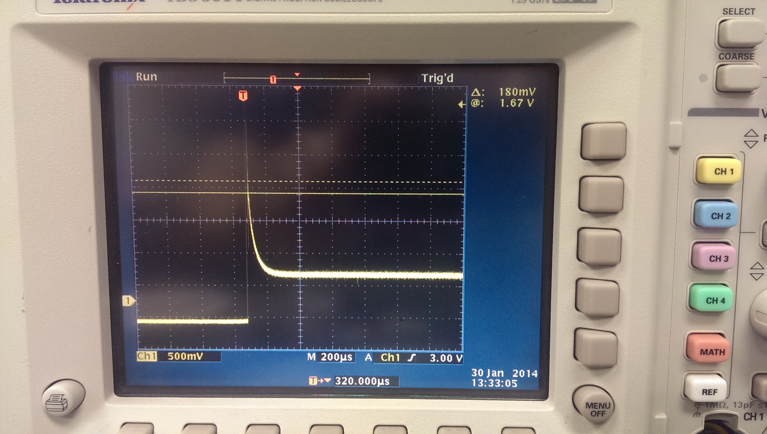
    Unfortunately, I did not see any significant difference.  Here is the output upon turning the OPA357 on without the diode:

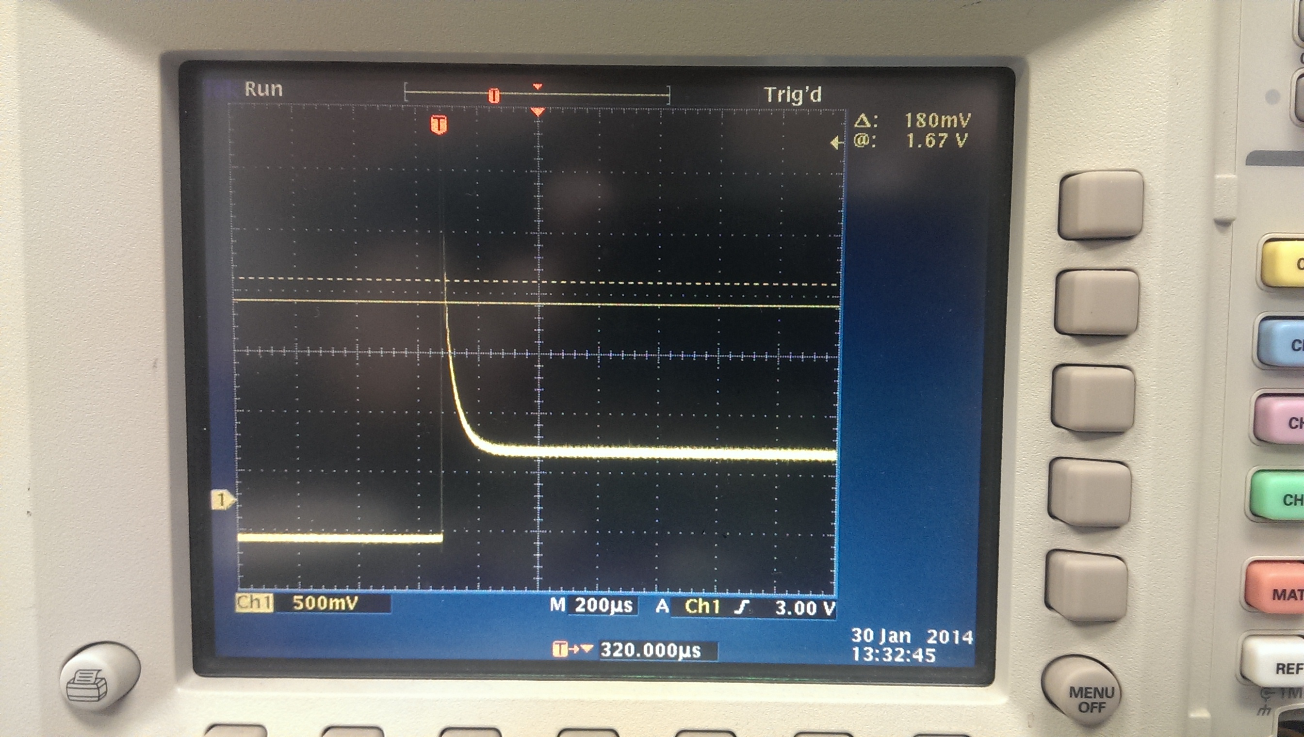
    and here is the output WITH the diode:

    Here are both outputs (slightly offset for clarity) together (white = without diode, blue = with diode):

    As such, might you have any other suggestions to avoid this peaking?

    Thank you very much, 

    Sean 

  • Hi Sean,

    Yes, I would say that adding the diode didn't do anything. The simulation and reality didn't match in this case.

    I am pretty certain now after discussing this issue with my colleagues that the charge in the circuit comes from the 24 pF diode capacitance that you had in your original schematic. When I simulate the circuit I find that the amplitude of the turn-on transient decreases as the capacitance value is decreased. Driving the capacitance to zero eliminates the transient. Unfortunately, the capacitance is inherent to the diode.

    Almost anything added to the circuit could alter the transimepdance performance so it is best to keep any solution simple. A possibility that I have been exploring is intentionally limiting the stage bandwidth somewhat by adding a small capacitance across the feedback resistor. This is commonly done for transimpedance amplifiers to keep them stable.

    Adding a 6.8 pF capacitor across the 500 k feedback resistor creates a lead-lag network out of the feedback path and op-amp input circuitry. The transient is eliminated in the simulation. This compensation technique is analogous to the compensated 0-scope probe. The capacitance value is very touchy and overcompensating causes the rising edge to sag. That is why a trimmer cap is used in the O-scope probe.

    Even if you were to implement this solution there is the risk that the output level will not be as accurate as you need during the time period you intend to take a reading.

    Regards, Thomas

    PA - Linear Applications Engineering


  • Hi Thomas, 

    Thank you once again for getting back to me.  I tried using a variety of capacitors across the feedback resistor and was able to reduce the initial peak.  However, as you predicted, the accuracy of the output immediately after turning the amp 'on' seems to be compromised (square wave input get distorted).  Perhaps the OPA357 isn't the best choice for our application since the output I am most interested in takes place for only about 20 microseconds after the I turn the amp 'on'.  

    The rationale for using an on/off-capable transimpedance amp was that we are flashing a very bright LED immediately before making our measurement.  Unfortunately, this bright flash saturates the system and compromises its accuracy immediately after the flash ends, which is when we want to make a measurement of a much, much dimmer signal.  As such, we thought that using keeping the amp 'off' until the flash was over would solve the problem.  Perhaps we'll need to think of another solution.

    Thank you again for all of your help.

    Sean


  • Hi Sean,

    Unfortunately, I do not think there is anyway around the turn-on transient using any operational amplifier having the enable/shutdown since it is coming from the photodiode capacitance. I've looked for some way to use analog switches to isolate the diode during the flash/saturation period, but didn't really come up with anything of much good.

    If I can be of help in some other way please don't hesitate to use this E2E forum.

    Best Regards, Thomas

    PA - Linear Applications Engineering