This thread has been locked.

If you have a related question, please click the "Ask a related question" button in the top right corner. The newly created question will be automatically linked to this question.

INA122 gain instability

Other Parts Discussed in Thread: INA122, INA333, INA326, TINA-TI

Good morning,

I am working on a pressure thermometer prototype, basically I need to amplify a signal at the output of a bridge configuration. I attached the design of a part of my system.

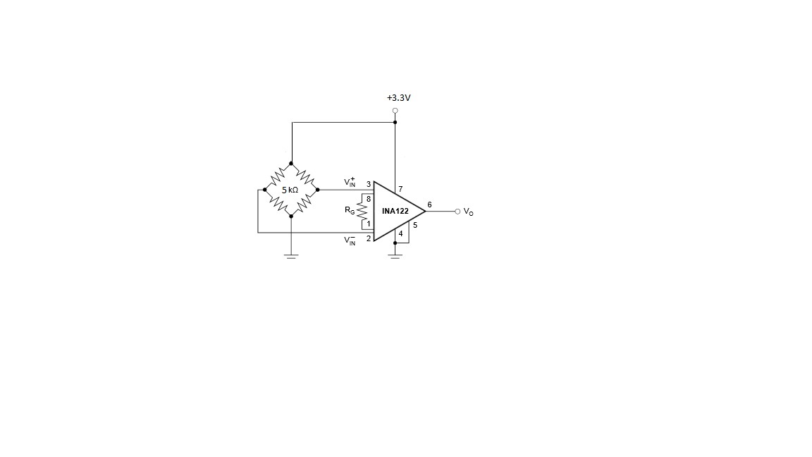
My first need is to measure very low signals some hundred uV and amplify the signal 100 times and give it to an A/D converter.

My system is supplied by +5V  so the INA and the bridge has the same supply, I used RG=40K (as suggested on  pag.7  of INA datasheet)  to have a gain of 10.  I wanted to try how the INA was responsive to the different inputs, I started by 500uV  and I stopped at 6mV;  I have noticed is that the gain changes depending on the inputs. How is it possible?

Attached you can find the table with the measurement results.

Vin (pin3-2)

Vout (pin6)

Calculated gain

300 uV

4.626 mV

15.42

400 uV

5.510 mV

13.775

500 uV

6.342 mV

12.684

600 uV

7.262 mV

12.10

700 uV

8.254 mV

11.79

800 uV

9.175 mV

11.45

900 uV

10.148 mV

11.27

1 mV

11.165 mV

11.16

1.5 mV

16.068 mV

10.7

2 mV

21.083mV

10.54

2.5 mV

26.097 mV

10.40

3 mV

31.173mV

10.30

3.5 mV

36.15 mV

10.30

4mV

21.083mV

10.30

4.5 mV

41.22mV

10.30

5 mV

51.35 mV

10.30

5.5 mV

56.41 mV

10.30

6mV

61.46 mV

10.30

I would really appreciate if someone could explain to me what happens.  What I need probably to add to the basic circuit I am using.

Then I will have another question concerning the lowest value I could give to the component to make it working properly...I mean, if I want to signal like  200uV  can I use the INA122?

I am looking forward for an answer.

Best regards,

Mia

  • Gain error and Offset Voltage are your dominating culprits.

    The INA333 is an auto-zero instrumentation amplifier that may help.

    -Ken

  • Hi Mia,

    The gain of the INA122 is varying because the device is not within the specifications of the output swing. The datasheet shows the output must be greater than (V-)+0.15V and less than (V+)-0.1V. With the device being supplied with +5V and ground means there must be an output of 150mV-4.9V. This would mean that with a gain of 10V/V the smallest voltage at the input would be 15mV. This can be corrected by adding a voltage to the reference pin to lift up the output voltage so that the output will be greater than 150mV. Or by adding a negative supply voltage, this way the output swing will be lowered and would also allow you to measure smaller voltages..

    Also with the INA122 there can an input offset voltage from +/-250uV to +/-500uV depending on the grade of the part. When trying to measure such a small input signal this can introduce significant error. To reduce these effects you might want to consider looking at the INA326 which has an input offset voltage of +/-100uV.

    I have attached a TINA-TI simulation for you to see how changing things such as supply voltages, gain, and reference voltages might effect the circuit.

    Hope this help!

    Tim

    INA122 test.TSC
  • Hi Tim,

    Thanks for the quick answer.

    I have directly tryed to make the output of INA 122 higher as the specifications of  datasheet....so I basically left the circuit as I posted but I have changed the value of RG and I made some test giving a gain of 1000 and 500.


    The amplifier works better but the gain still floats a little bit....There is something else I can do to optimize its performances?

    I will try also your circuit just to see which will be the better solution for my purpouse.

    I have a question about INA326....could I measure little value like 20uV at the input? I'm also doing tests on the sensor prototype so everyday I discover something new.... and now I know that I need to measure values around 10uV-20uV.

    Vin (pin3-2)

    Vout (pin6)

    Calculated gain

    305 uV

    190.4 mV

    617.37

    404 uV

    239.6 mV

    593

    503 uV

    291 mV

    578

    603 uV

    291 mV

    482

    716 uV

    343.7 mV

    480

    804 uV

    447.7 mV

    556

    912 uV

    503.3 mV

    551

    1.010 mV

    555.7 mV

    498

    1.497 mV

    804.5 mV

    537

    2.009 mV

    1.3261 V

    663

    2.511 mV

    1.0679 V

    425.28

    3.017 mV

    1.5869 V

    525


    Mia

  • Hi Mia,

    In order to measure such a little value (10uV-20uV) at the input using any TI instrumentation amp you will need to calibrate out the input offset voltage. This is because our lowest offset voltage device (INA333) has +/-(25+75/G)uV of offset voltage, which is greater than your input signal.

    Please see figure 2 of the INA122 datasheet regarding offset trimming.

    -Tim Claycomb