This thread has been locked.

If you have a related question, please click the "Ask a related question" button in the top right corner. The newly created question will be automatically linked to this question.

Audio balanced line driver

Other Parts Discussed in Thread: INA217, DRV134

Dear,

I want to amplify signal for Shure 514B microphone placed 40 meters from amplifier. I'm going to use INA217 and DRV 134 but I don't sure if my design is correct. I don't need phantom power.

I have some doubts, my microphone is dynamic with 150ohm, Is INA217 input FET or Bipolar?  Do I have to put capacitor between INA217 and DRV134? Is necessary a capacitor at each INA217 input?

Please, Can anybody help me?

Best Regards

SAMUEL


  • Hello Samuel,

    The INA217 is bipolar.

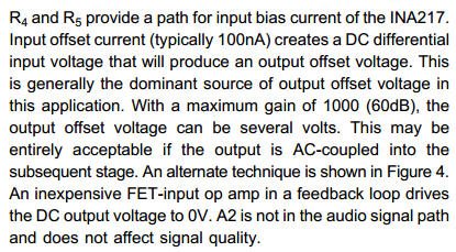
    Placing a capacitor between the INA217 and DRV134 will remove dc errors introduced by the INA217. The example discussed in the data sheet is shown below.

    Similarly, the input capacitors block any dc voltage from the microphone. However, in order for the INA217 to operate properly the input stage requires a input bias current return path...hence the input resistors to ground (R35 and R36 in your schematic). The RC combination is also a high pass filter with a cutoff frequency of 1/(2*pi*R*C). In Figure 4 of the data sheet, the capacitors are 47uF, which create a cutoff frequency of ~1.5Hz with the 2.2kohm resistors. In your schematic the 0.1uF caps create a filter with cutoff frequency of ~723Hz, which is well into the audio range. Therefore I recommend increasing the value of your capacitors.

    Just in case, I recommend adding the input stabilization network shown in Figure 2.  You can start testing by shorting the inductor and not populating the resistor.  If you experience instability, you can then add the components shown in Figure 2.

    Finally, please note that with a +/-5V supply your input common mode range is only +/-1V and the output swing is only +/-3V.  You should make sure that your input signal (and input referred errors such as offset voltage and input offset current) and desired output signal (which is the product of your input and gain) are within those ranges.

    I hope this helps!