This thread has been locked.

If you have a related question, please click the "Ask a related question" button in the top right corner. The newly created question will be automatically linked to this question.

Please help me remove oscillation

Other Parts Discussed in Thread: OPA637, OPA627, OPA134

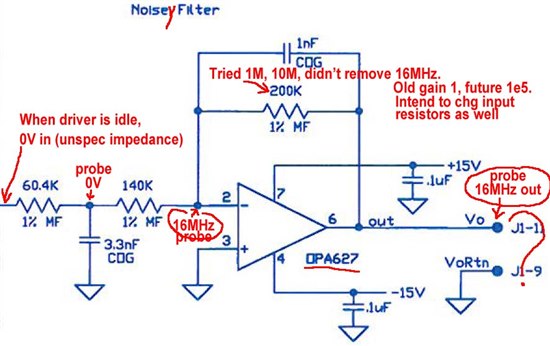
I inherited a special purpose amplifier that included the noise(y) filter below.  Everything in front of the noise(y) filter is working properly.  When things are idle up front, I get about 0V coming into this section.   However, this circuit is oscillating, introducing a 16MHz signal.  

I'm not sure how to get rid of it.  Your assistance would be greatly appreciated.

Do note that I read about the OPA637 being stable above gain of 5.  Also, due to an unrelated problem upstream, I want to increase the gain of this stage from -1 to -1e5 (-100,000).  So I tried putting in a larger feedback resistor, but this didn't change the noise at all.  So, I don't know what's unstable about this circuit.

Note also that I confirmed that the 16MHz is not present on the input, or at the middle of the incoming Tee filter.  I checked this just to make sure the problem wasn't with my scope or ground, or some snafu like that.

  • By the way, the schematic called for OPA627, but the build I find in my hand has OPA637.  I've been studying further and have figured some things out, but not yet all.  It appears the OPA627 has a 75 degree phase margin, but the OPA637 has little or none.  The datasheet says NOT to use the OPA637 in this configuration, which is what was done.  I have two choices perhaps.  Remove the OPA637 and replace it with an OPA627.  Perhaps this will eliminate the oscillation.  However, I don't think I can run the gain up as high later as the desired -1e5, using the OPA627 as I could with the OPA637.  So, my other choice...  I cut through one leg of that 1nF feedback cap and the OSCILLATION WENT AWAY.  So, using my newly learned (re-remembered after decades) terms, it seems that the original designer put the 1nF there to compensate the OPA627.  However, it's not appropriate for the OPA637 can causes instability.

    So maybe I just move forward with the OPA637 and no cap.  Or maybe you have a better improvement for me.

    BTW, I cut the cap while having a 10M in place of the 200K, so my gain should have been around 50 at this time.  I'll need to later change those 60.4K and 140K (and 3.3nF) to smaller values to avoid needing unreasonably high feedback resistance at the 200K location.

    I'm still seeking other advice on alternative ways to make this stable.  Thanks in advance.

  • Hello,

    I am wondering why removing your feedback cap should make your system more stable, generally I would test with more capacitance to get rid of unstable behaviour, have you tried introducing 100nF in your feedback path, this should make your whole Bandwitdh a facotr 100 smaller but stable.

    And just not to confuse it, you state your opamp is stable with a minimum gain of 5 but you are working it on a lower gain, so why should it be stable then? Did I get that right?

    Other approaches, does it have to be the OPA627 series? isnt that a rather expensive sophisticated one, couldnt you use or at least for circuit testing use a jelly bean one like opa134, I think we did use your combination also and switched back to the 134, but I am not sure right now, perhaps I am confusing something.

    Those are my ideas, hope you keep this up with your solutions.

    Greetings,

    Seb

  • Seb,

    Thanks very much for your suggestions.  I'll take them under advisement.

    To answer your questions...  

    1) I removed the feedback cap because the OPA637 datasheet says that such a feedback cap will make it unstable, which is exactly what happened.  See datasheet page 8, second paragraph, "Circuits with a feedback capacitor (Figure 1) place the op amp in unity noise-gain at high frequency. These applications must use the OPA627 for proper stability."  Well, the schematic says OPA627, but the board actually has an OPA637 on it.  It was easier to remove the cap today.  I have OPA627's on order for a couple days from now, so I can try putting the cap back.  This all relates to the OPA637 having different internal compensation and thus less phase margin.

    2) Recall, my intent is to have gain=1e5 in this stage, even though the circuit is now at gain=1.  I did replace the 200K resistor with 1M, so the gain=5 right now.  So now the circuit is consistent with the datasheet talking about only using the OPA637 for gain of at least 5.

    3) Regarding the OPA627/637, the original schematic had these.  I'm not married to that idea.  I do need extremely low noise because of the high gain.  I searched and could not find anything any better than the OPA627/637.  The cost relative to the full build is not a serious issue.  Nevertheless, I'll consider your OPA134 suggestion.  I'm operating around 10Hz, and the OPA627/637 has about 15nV/Hz^-2 voltage noise typ (page 2).    The OPA134 is spec different in the table, but on page 4 bottom left graph seems to be about the same... good.  Open loop gain (page 5, top left graph) seems to be similar, but I'm not sure about the phase diagram.  This makes me wonder if I would need different external compensation to avoid oscillation. I don't know a lot about this subject.  Offset voltage seems to be a big loser here, with the OPA134 having 1mV compared to OPA627/637 having 40uV.  Input bias current not too different, at 5pA for OPA134 and 1pA for OPA627/637.  Well, actually, in an earlier stage that 5pA vs 1pA *might* be signficant.  OVERALL, I don't see the OPA134 providing any advantage OTHER than cost.  And since cost is not a problem in this instance, I think I may be better off leaving well enough along.

    Again, thanks for the suggestions.  I've learned or remembered quite a bit in the last two days about opamp circuits.  I'm still not sure of everything.  And while I've eliminated the 16MHz by removing the feedback cap, down at a much lower voltage level I still get a 60Hz noise (60mV p-p) that I need to get rid of next.  It's not present at pin 2, but it is present at pin 6.  I added 1uF tantalum caps to the +/-15V power pins 4,7.  Didn't help.  I added RC to the output, but it interacted with internal compensation, giving me 1/100th or 1/1000th the speed.  That is, when 1/RC=100Hz, the filtering was on the order of 0.5Hz.  I reduced R dramatically so that the filtering speed wasn't a problem, but the 60Hz came back.  After all, at this point I was trying to separate 60Hz noise from 10Hz square wave (thus needing better than 10Hz response because square-ish, closer to 100Hz).  I'm not sure I'm going to be able to get rid of the 60Hz until I actually build my own, presumably much superior, board.

    Nevertheless, any other suggestions are greatly appreciated.