This thread has been locked.

If you have a related question, please click the "Ask a related question" button in the top right corner. The newly created question will be automatically linked to this question.

Current Sensing using LM722

Other Parts Discussed in Thread: DRV8833, LMV722

Hi

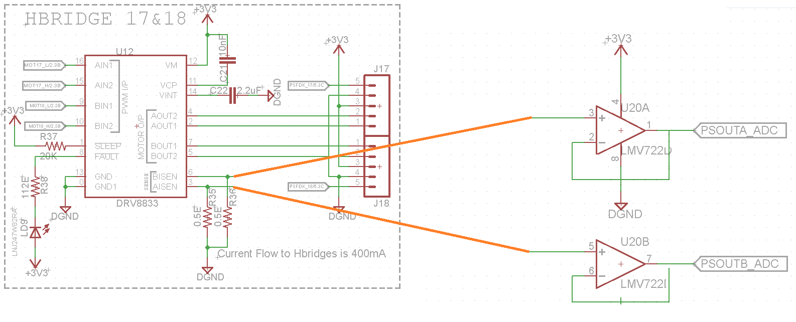
I need to measure the current sensing for Hdridge driver, in my design iam using DRV8833, the Hbridge driver have current sensing pin. so iam using current sense amplifier to measure the current.

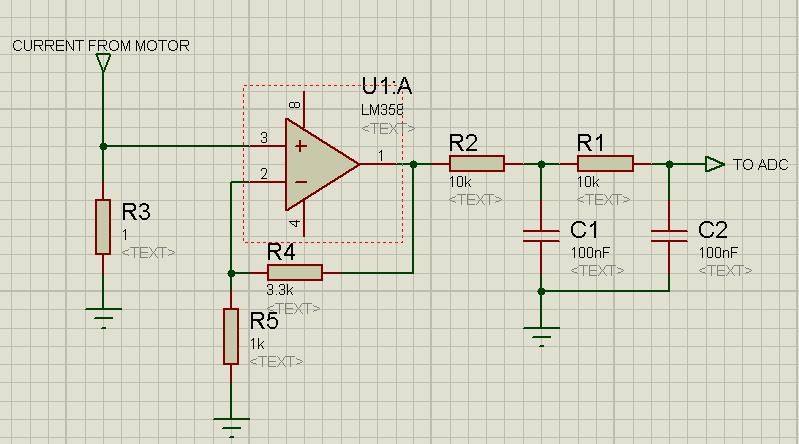
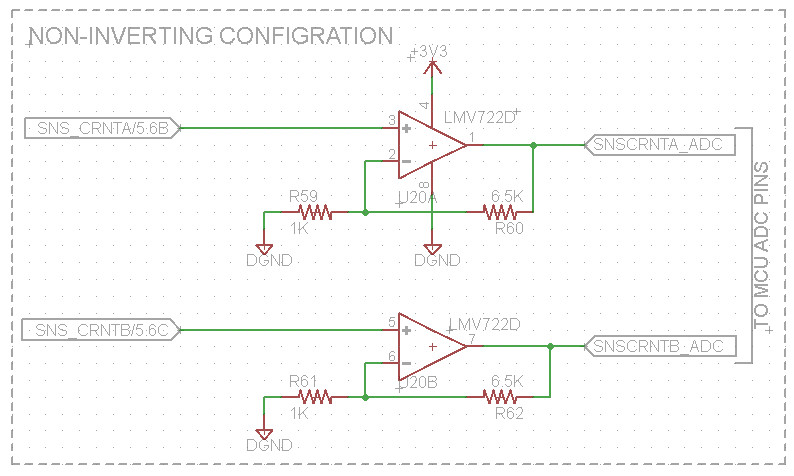
please find below image of my Amplifier circuit, here iam using LMV722 amplifier to measure the current thru shunt resistor (0 to 250mV),  so as per the voltage differences we can calculate the current flow thru the motor

The output of the amplifier is connected to ADC pins of the Microcontroller. I would like to request your thoughts on the design. please find below image.


Regards

Anil

  • Hi,

    You cannot use the LMV722 as you have showed in your circuit. Either you need to have the op-amps in the unity gain configuration OR non inverting configuration.

    Best regards

  • Hi Gehan,

    Thank you so much for your response, please find below unity gain configuration, just inserted the feedback.

    I would like to know What type of configuration is better for current sensing,  Unity gain or non-inverting configuration, hope you have experience in current sensing, could you please elaborate your views on these.

    if i use Non-Inverting configuration, How to decide the values Resistors (Feedback resistor and other resistor which is connected to inverting terminal of op-amp)

    if i use unity gain configuration, like below is there any drawbacks?

    Iam giveing amplifier output to the ADC pin of Micro controller for measurements.

  • Hi,

    Using the buffer configuration or positive gain configuration is up to you. The difference is that the latter will allow you to use the full range of your ADC.   

    However if you connect the opamp output to the ADC you will get the instantaneous current. Since the motor motor is switched ON and OFF rapidly using the PWM signal, the values you measure from the ADC will be all over the place (because the current going to the motor will almost take the shape of a square wave + there might be a lot of switching noise). For what purpose do you need to measure the current?

    I myself measured the motor current for one of my applications and for that I used something like this.

    The maximum instantaneous current from the motor was about 1A and hence the maximum input voltage to the opamp was about 1V. So with a gain of 4.3 the maximum voltage output from the opamp is about 4.3V. When this goes through the LPFs it becomes an average voltage which is proportional to the average motor current.

    The microcontroller I used accepted an input voltage range of 0-5V and hence the gain I choose was more than small enough.

    If you are using a 3.3V microcontroller choose a gain so that at maximum motor current the input to the micro does not exceed 3.3V. However this may change if you are using an external voltage reference.

    Best regards

  • Hi Gehan,

    Thank you so much for your inputs, Please find below image i modified according to our requirement. I designed the Hbridge for Maximum current flow thru the motor is 400mA.so the maximum input voltage at opamp is 0.4V.

    output gain is 3 and output voltage is 3V, so i can use opamp output is directly connecting to ADC of Micro controller. micro controller will work in 3.3V supply.

    so i can assume the variation of 3V output is variation in current flow thru the motor (I designed the values of 6.5K, 1K). I need to sense the current flow to the motor, if current exceeds or decrease threshold level, motor stops, to avoid this, we are monitoring the current.

    Please suggest if my understanding is wrong.


  • Hi,

    Looking at page 9 of the DRV8833 data sheet there seems to be an on chip  current control circuit implemented. It says that at a sense voltage of 200mV the current will be chopped (limited). So if your motor consumes a MAXIMUM instantaneous current of 400mA put a 0.5ohm sense resistor otherwise the inbuilt current limit circuitry will be activated in normal normal operation (if you use a 1ohm resistor at 200mA the IC will start limiting current).   

    The gain of your opamp is 7.5 (gain = 1+R60/R59 = 1 + 6.5k/1k = 7.5) but yes the max output voltage will be 3V. 

    The best thing to do is to breadboard the circuit and test it.

    BR

  • Hi Gehan,

    Thank you so much for your response.

    if you look at my first thread, i did 0.5ohm Resistor added across sense pin for 400mA of current, so as per the op-amp configuration, for 400mA of current opamp will give 3V output maximum, so variation in the input, the output voltage will very. this will helpful identify variation in the motor current.

    Please find below circuit,  please suggest for further improvements in the schematic. i tried with simulation, its exactly getting 3V and also i tried with variation input, its also changing the output of the opamp