This thread has been locked.

If you have a related question, please click the "Ask a related question" button in the top right corner. The newly created question will be automatically linked to this question.

Error Analysis for Instrumentation Amplifier

Other Parts Discussed in Thread: INA333, INA149

Hi all. I'm analyzing the following circuit and I've to establish if the INA333 is a good choice for this application, working about Error Budget Analysis.

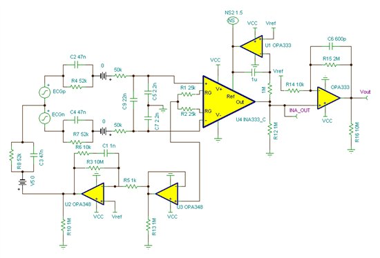
I have to express the errors in "parts per million". Can someone explain me the various contributions I've to insert in my calculation? In which resistor the Input Offset Current flows to create an Offset Votage?

Thanks in advance.

Regards, Vincenzo

  • Hello Vincenzo,

    The error due to input offset current depends on the mismatch between the source impedances. For example, let's consider only the 50kohm protection resistors.

    If their tolerance is 1%, the greatest mismatch occurs when one is 49.5kohm and the other is 50.5kohm. The product of the impedance mismatch with the input offset current is 0.2uV.

    The challenge for you is to determine the source impedance mismatch. This probably depends on many factors such as electrode type and their location on the skin.

    Perhaps you could mitigate the mismatch by installing known, well-matched resistors for the input bias current (see Figure 34 from data sheet). Of course you will want to make their impedance small enough to dominate the parallel combination with the electrode/skin impedance. However, you will still need to understand the magnitude of the electrode/skin impedance for your configuration.

    Concerning error in ppm, here is a blog post that has some example calculations.  It is not specific to ECG but the equations may be helpful.

    http://e2e.ti.com/blogs_/b/precisiondesignshub/archive/2014/03/14/how-to-calculate-the-effects-of-resistor-self-heating.aspx

    The INA149 data sheet has an example error budget analysis (Table 2). Though completely different applications it may be useful for your calculations.  

    DC errors are generally minimal when compared to the electrode-skin offset.  They are also generally removed using the integrator, U1.  Therefore I would focus your analysis on noise.

    Finally, I don't know if you have seen the following link.  It has some good reference material.

    http://e2e.ti.com/support/amplifiers/precision_amplifiers/w/design_notes/2437.ecg-heart-signal-acquisition.aspx

    I hope this helps.

  • Thanks Pete. Your post was very helpful, I'll study the documentation you suggest me. Instead, for power-line filtering ( 50 Hz or 60 Hz), is correct filtering after the INA-amp with a notch active filter (e.g Twin-t type)? Why this operation is done after instrumentation amplifier?

    Thanks again. Regards.