This thread has been locked.

If you have a related question, please click the "Ask a related question" button in the top right corner. The newly created question will be automatically linked to this question.

THS7347 - Series resistor connected at the monitor output

Guru 19785 points
Other Parts Discussed in Thread: THS7347

Hi Team,

Could you please help us support our customer about THS7347 ?

[Question]
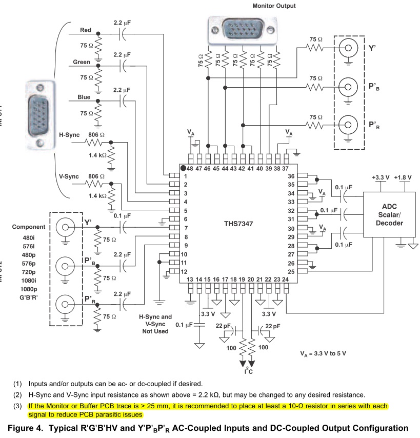
There is a following description in the datasheet Figure4.

"If the Monitor or Buffer PCB trace is > 25 mm, it is recommended to place at least a 10-Ω resistor in series with each signal to reduce PCB parasitic issues."

Could you please give us detail explanation why and where you would need >10 Ohm resistor ?
Do you need to add the resistor addition to 75 Ohm in the figure ? We appreciate if you could also tell us how to choose this resistor value.

[Background]
Our customer is facing a problem that they have noise issue in the output video.
They have long transmission line trace and had connected the 75 Ohm resistor 130mm away from THS7347 monitor output pin.

However, by connecting this 75 Ohm resistor much closer to the THS7347 monitor output pin, about 10mm, this noise issue were solved.

Thanks in advance.

Best Regards,
Kawai

  • Hello Kawai,

    It is usually recommended to terminate the output of THS7347 with a series resistor close to the output pins because for long pcb transmission line traces, the load could become fairly inductive. Driving long transmission line traces without proper input termination is usually accompanied by ringing effects.

    The proper solution would be to place an appropriate input termination, which in this case is 75ohms because the termination is 75ohms as well, close to the source/output pins of THS7347 and then drive the long transmission line. You don't need to add an additional 75ohm series resistor but only move this resistor closer to the output pins of THS7347.

    I hope that solves the issue.

    Best Regards,

    Rohit

  • Hi Rohit-san,

    Thanks for your comment.

    It seems that the device output is oscillating in the customer environment.
    Could you please help us on the following  three more question ?

    [Question]
    Is the oscillation due to the load capacitance of the transmission line trace ?
    If 75 Ohm resistor is far away from the pin, device output will have load capacitance of the trace length.
    I believe this is leading to shift phase which decreases phase margin.

    Do you think my understanding is correct ?

    [Question]
    When using this unity-gain buffer output, Is there anything you must be careful to prevent oscillation ?
    I understood 75Ohm resistor must be connected close to the pin.
    Is there anything else ? (PCB/schematic Design, limitation... )

    [Question]
    Do you have Gain/Phase margin measurement data of this unity-gain buffer ?
    If you have the data, could you share us the information ?

    Best Regards,
    Kawai

  • Hi Takushi-san,

    Could you please post oscilloscope plots of the output oscillations? Is the customer schematic same as the one attached above?

    It might be that the oscillation is due to driving an inductive load at the output of THS7347 which is caused due to long transmission line traces. I think yeah, because of that the noise gain would reduce and the phase margin would degrade potentially causing oscillations.

    Placing the 75ohms close to the output pins should help this because ideally amplifiers like to see a series resistive termination at the output and then drive into a transmission line. Without a series resistive termination, the signal looks like its driven from an unterminated low impedance source into an inductive load (transmission line). I dont think there should be anything else in the PCB/schematic change which you should do.

    I dont think I have Gain/phase margin measurement data for this unity gain buffer at this moment handy. I would need dig up the information.

    Best Regards,

    Rohit

  • Hi Rohit-san,

    Thank you for your comment.

    As I received their data as a confidential information, I can not post here.
    I could send you the waveform data via Email.
    Could you give me an Email to the my Email address ?

    Difference is just where 75 ohm is placed.

    Best Regards,
    Kawai