Other Parts Discussed in Thread: ACF2101
Hi!
I want to use ACF2101 as a photodiode amplifier.
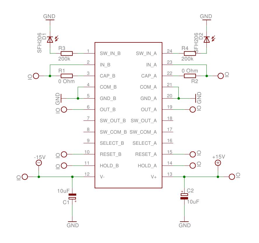
I connect the ACF2101 as in typical connection on Fig 1a in datasheet, photodiode connected only to one channel. I am not using select switch, the supply voltage is +-15 V.
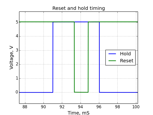
Typical hold pulse duration was about 5 mS, reset 1.5 mS and the reset pulse is shifted by 2.3 mS from the beginning of the hold pulse, pulse repetition rate 10 Hz, and the integration duration 95 mS.
At low current levels (photodiode was in complete dark, expected dark current about 250 pA) the output of the ACF2101 after starting integration cycle goes up (for about 5 mV in 100 mS), instead of going down to negative voltages, see figures below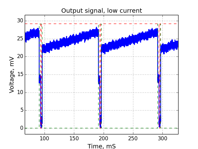
Zoomed portion around the end of integration cycle: 
Green dashed line is scaled hold signal and red - reset.
When I increase the current the slope of the output signal is decreasing, so at some point it can be flat and when you increase it more it looks something like this: 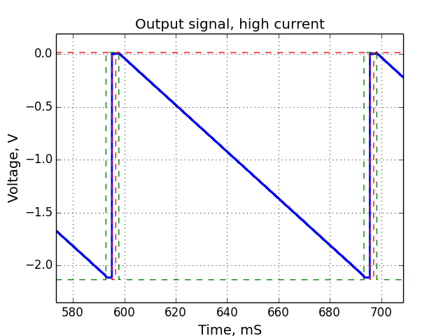
Zoomed portion around the end of integration cycle: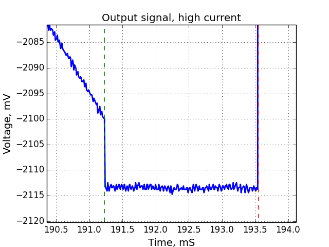
And the beginning of the integration cycle: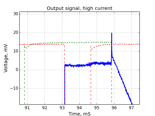
Also here are the timing diagrams of the hold and reset separately: 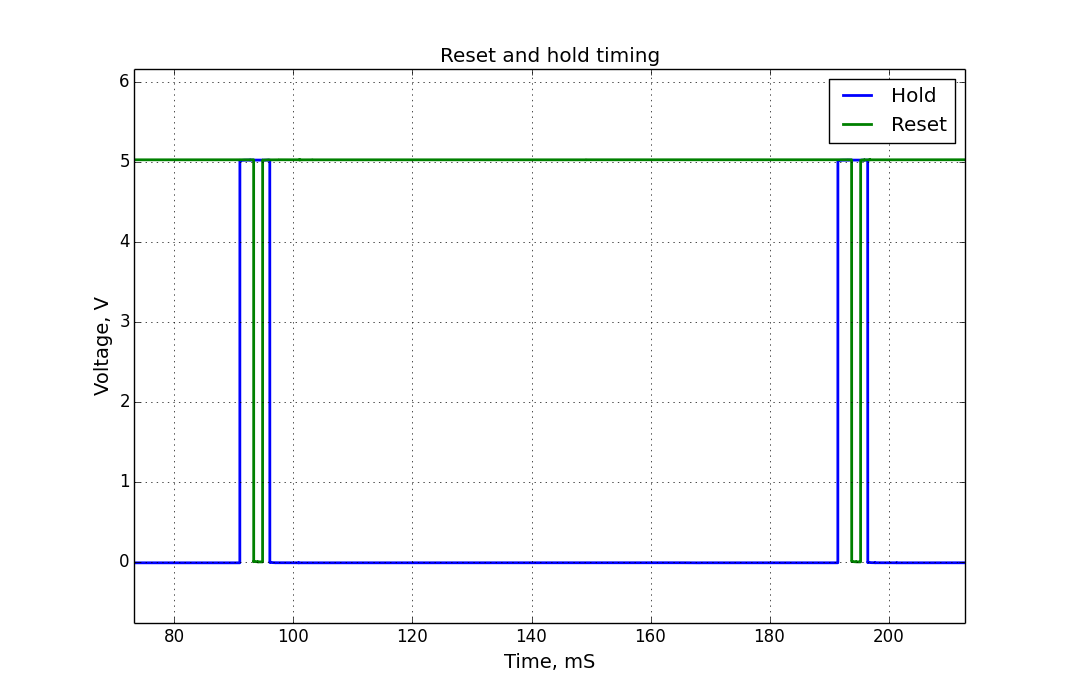
So my questions are:
1. why does the output voltage goes up at low current levels?
2. why does the voltage drop at the beginning and at the end of integration cycle is so big (around 15 mV)?
and why the drop at the beginning of the integration cycle is positive? (if I understand it correctly it should be negative)
So far I have tested two devices and both channels on those, qualitatively they all behave similar way.
I will be appreciate for any help with this issues,
thank you!