This thread has been locked.

If you have a related question, please click the "Ask a related question" button in the top right corner. The newly created question will be automatically linked to this question.

RTD Sensor with OPA2335 Problem

Other Parts Discussed in Thread: OPA2335, ADS1220, ADS1247, TINA-TI

Hello there,

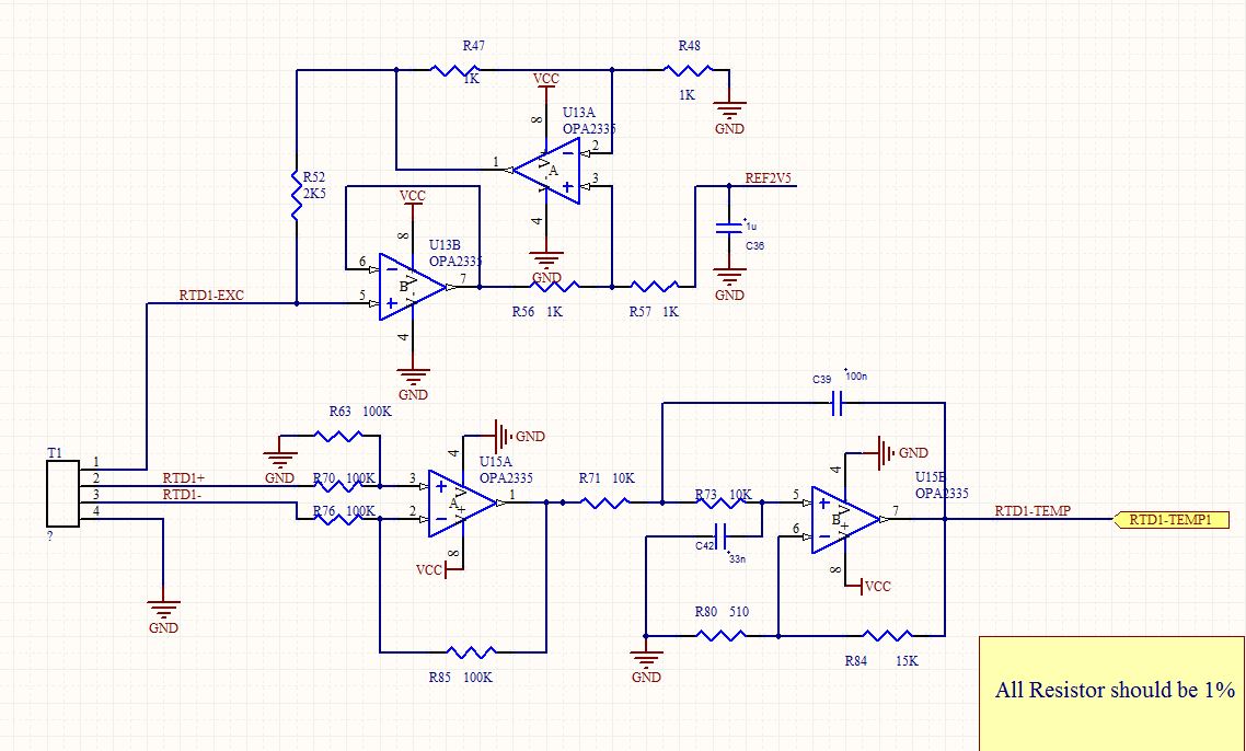
I am using OPA2335 for signal conditioning RTD sensor. my schematic is attache here


The Vcc=5V, Vref=2.5V, Iexc=1mA

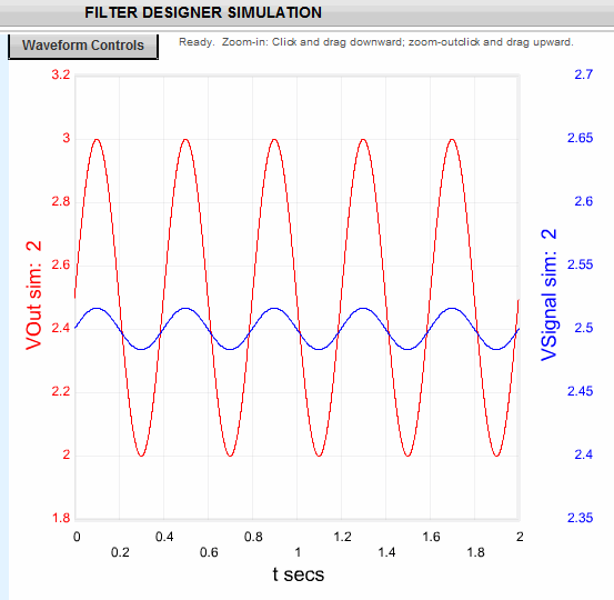
The output from the first stage is around 109mV analog signal at room temperature but the output from second stage Sallen key low pass filter is PWM signals that are average to around ~3V. If I try to feed these signals to ADC it is jumping a lot. so is it normal that I should expect PWM signals at the output or opamp is operating in saturation region.

-Tushar


  • Hello,

    It sounds like your active filter is oscillating.  Without performing detailed analysis, I have a feeling that this is likely because of the high-gain applied in the filter (15k/520) which generally increases the Q of the filter and thereby decreases the stability.  

    In general, to optimize your design for noise performance it is best to place your gain in the first amplification stage so the noise of the previous stages is not gained by the later gain stages.  Therefore I recommend that you increase the gain in the first stage and set the gain of the 2nd stage to 1 or 2V/V and see if the circuit begins working more appropriately.

    Also, consider the ADS1220 or ADS1247 for a single-chip RTD acquisition solution that includes the current sources, programmable-gain-amplifier (PGA), and 24-bit Delta-sigma ADC.

  • Tusjar,

    I am instested in your circuit. It is difficult to read the actual resistor and capacitor values in your filter, so can you supply them to me? Also, what ADC are you using and is this ADC at the output of the filter?

    Also, I have a few questions about the filter characteristics.

    Corner frequency = ?

    Approximation type = ? (Butterworth, Bessel, etc)

    Gain = ?


  • The ADC I am using is from Phidgits http://www.phidgets.com/products.php?category=0&product_id=1010_0

    The corner frequency is around 250Hz

    Chebyshev  Approximation

    Gain 30.41V/V

    I am attaching the image of the schematic (Please click on the image to view on full screen). I think my filter is unstable which gives oscillating behaviour, but not sure if I am correct. could you help me with this the correct values to use for filter.

  • Tusjar,

    You are correct. This filter will oscillate. I am using your inputs and finding that the resistors and capacitors are not correct. My recommended circuit would be:

    There are a few things that I changed with your topology. Please look at the R3 connection. The voltage that should be placed here is 1/2 way between the power supplies. If you are using a 5V supply, that voltage would be 2.5V.

    I generated this filter using WEBENCH Filter Designer. In this program I set fc to 250 Hz, Gain = 30.41 V/V. I then selected "Pick Filter Response" and selected a response of Chebshev with a filter order of 2. With this Chebyshev selection the ripple with be 0.2 dB. Please let me know if you want a different ripple.

    Once your design this filter in Filter Designer you can run an ac, step response, and sine wave simulation. In my simulattion runs my plots looked like this.

    I then verified this performane using the TINA-TI simulator. My TINA file is attached.

    SS_SK_2P_lowpass_nonunity.TSC
  • Hello Bonnie,

    You were right My filter was oscillating because of incorrect value so I took correct values from filter pro software as suggested and it works fines, output is also pretty much stable.

    Thanks,

    Tushar

  • Tushar

    You are very welcome. Don't hesitate to ask for more help in the future.