This thread has been locked.

If you have a related question, please click the "Ask a related question" button in the top right corner. The newly created question will be automatically linked to this question.

IR proximity sensor

Other Parts Discussed in Thread: TINA-TI

Hello,

I want to build a circuit with a photodiode to detect 56 khz modulated ir signals. as per my knowledge, I have to build a Band pass filter using op amp which allows only signals around 56 khz freq.

So,I am not able to find out the component values to be used for this purpose. please help me out how can i select the resistor and capacitor values. Is a normal active band pass filter sufficient for this purpose or any other changes need to be made??

I am a newbie in this field . please dont mind to explain in detail

Regards

  • Hello Varun,

    Op amp based active band-pass filters are practical for a 56 kHz center frequency providing reasonable expectations in terms of filter response requirements are established. By that I mean don't try and set a very narrow pass-band bandwidth (low Q), don't set the filter up for high gain, and keep the filter response simple such as one having a.Butterworth response i.e.don't select a Chebyshev response  Otherwise, the required op amp gain-bandwidth (GBW) may become exceptionally high and the component tolerance requirements very tight.

    TI has a couple of active filter synthesis tool that you can use to help develop the filter, FilterPro and the Webench Filter Designer. Since you don't have much experience with active filters FilterPro would be the tool I would choose to start with. You can find these tools on the TI web site at:

    http://www.ti.com/tool/filterpro

    http://www.ti.com/lsds/ti/analog/webench/webench-filters.page

    My suggestion is to try synthesizing a 56 kHz band-pass filter having a gain of 1 V/V, a Q of 10, or less (fCENTER/ BW), a Butterworth response and force a filter order of 4. You can set the filter up for a higher order, but the number of stages increases and the stage Q may increase. Note that the Sallen-Key (SK) and Multiple Feedback (MFB) topologies these tools synthesize should be limited to a Q of 10 for a band-pass filter. Otherwise, the response may deviate from the expected.

    The programs will list the op amp gain-bandwidth (GBW) requirements for each filter stage. Make sure you select an op amp having sufficient GBW. Also, you will need quality passive components for accurate response. Consider 1 %, or tighter, tolerance resistors, and NPO/C0G, or film, capacitors with the tightest tolerance that can be accommodated. The more exact you can make things, the more precise the filter response will be.

    Regards, Thomas

    PA - Linear Applications Engineering

  • Hello Thomas,

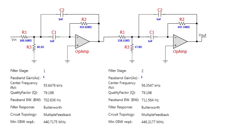
    Thanks a lot for your reply. I have checked the filterpro software and have designed a BPF as per the specifications you said and have obtained a 2 stage bpf. I have selected a bandpass BW : 1Khz and stopband BW: 10khz. I have attached the obtained result

    1. As per my knowlwdge, 1st stage is for High pass and second stage is for low pass. what are the advantages of using two stages. can i design a single stage BPF. If so how can i?

    2. I have looked into calculation of resistor and capacitor values for Active BPF in this website but couldn't get an exact idea

    http://www.electronics-tutorials.ws/filter/filter_7.html

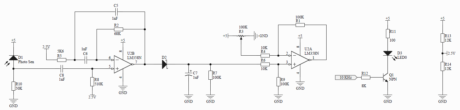
    I have found a circuit diagram in internet for Band pass at 10khz .

    3. I dont know if it is correct. But it would be very helpful if you could explain the main parts of circuit ( for ex: what is the use of second part of circuit i.e, after the peak detector and also about peak detector). If the circuit is correct which values could i change for 56 khz band pass ( with calculations)

    Please don't mind for my silly doubts. I have no other useful help around me. I am trying to learn on my own.
     

    Thanks and Regards,

    Varun

  • Hello Varun,

    Here are my responses to your questions:

    1. As per my knowlwdge, 1st stage is for High pass and second stage is for low pass. what are the advantages of using two stages. can i design a single stage BPF. If so how can i?

    Each stage is a band-pass stage providing both a low-pass and high-pass response. The product of each of their individual responses produces the overall band-pass response. The advantage of two stages, over one, is the roll off outside the pass-band is 2x (40 dB) per decade, instead of 20 dB per decade. The higher roll off provides better rejection of signals outside the pass-band.

    2. I have looked into calculation of resistor and capacitor values for Active BPF in this website but couldn't get an exact idea http://www.electronics-tutorials.ws/filter/filter_7.html 

    That site provides a nice introduction to active filters, but isn't an in-depth treatment on the subject. There is a lot to the subject of active filters and books have been written on them. FilterPro, and the Webench Filter Designer tool, take care into account all the filter requirements and make solving the filter easy.

    3. I dont know if it is correct. But it would be very helpful if you could explain the main parts of circuit ( for ex: what is the use of second part of circuit i.e, after the peak detector and also about peak detector). If the circuit is correct which values could i change for 56 khz band pass ( with calculations)

    The schematic is a little difficult to see; however, here is what I think it is accomplishing: The first stage has the photodiode input which is ac coupled via an RC to the first amplifier. The input RC sets up a high pass function. The stage itself looks to be a band-pass filter of some sort. It is followed by the Schottky rectifier with a parallel RC to ground that sets up the time constant for the peak detect. The second amplifier is a difference amplifier with a gain of 10 V/V. The dc level set by the R3 potentiometer will be subtracted form the rectified dc level and their difference will be gained up by 10x.

    My suggestion is you set up you circuit idea using the TINA-TI simulator software. The software is very easy to learn and apply, and you will be able set your circuit up and test it. You will be able try different op amps and see how they respond in the circuit. You can find the software here:

    http://www.ti.com/tool/tina-ti

    I hope this helps.

    Regards, Thomas

    PA - Linear Applications Engineering