This thread has been locked.

If you have a related question, please click the "Ask a related question" button in the top right corner. The newly created question will be automatically linked to this question.

opa129

Other Parts Discussed in Thread: INA116, LMP7721

hai,

      i am using opa129 to detect current of the order 10^-12(pico amperes) . the gain of my opamp is 1 giga ohm and i have connected in inverting configuration.

when no input is applied to the opamp . i get square waves at the output. the magnitude of the square wave is +-15 volts equal to the +-Vcc what i have applied.

please tell me the reason for this? and the opamp is also not detecting any current. the output is always a square wave.

please help

  • Deepak,

    The square wave on the output of your amplifier is caused by the output saturating - the output is trying to go higher than the voltage rails, and they "clip" around the levels of your power supply. Since you are seeing this with no input, one of two things is happening:

    1) I assume when you say the gain is 1 gaga ohm, it is 1 gigaV/A - what size resistors are you using? You could be amplifing resistor noise or any input noise of the op amp.

    2) You need to check the stability of your amplifier. Do you have any load capacitance? High resistance and low capacitance can push your pole to lower frequencies, causing your amplifier to become unstable and oscillate. If it begins to oscillate, you will soon see saturated square waves on the output. This seems more likely of the two causes. Please refer to TI's app note on designing your amplifier to be stable:

    http://www.ti.com/lit/an/slyt367/slyt367.pdf


    Michael Brantley


  • i am using normal sized resistor only. i am not using any output capacitors. please suggest me a method to make the circuit stable to detect the current.

  • Hi Deepak,

    The best device for this application is the INA116. This device has a max input bias current of +/-25fA (versus 100fA with the OPA129) which will work well for your application. It also uses guard rings to prevent leakage currents at the input. When using this device be sure to follow the Circuit Board Layout and Assembly section of the datasheet. The maximum gain of the INA116 is 1000V/V, if additional gain is needed a second gain stage can be added or the shunt resistor can be increased.

    Hope this helps!

    Tim Claycomb

  • i went through the datasheet of INA116. it is a voltage amplifier if i am not wrong.  i want to amplify currents of the order pico amperes. so i want a current to voltage amplifier or a trans -conductance amplifier.  so are you sure that i can still use INA116 instead of opa129.

    and how is the maximum gain of INA116 1000V/V. does it not depend on the feedback resistors? so by increasing the feedback resistor wont it change?

  • Hi Deepak,

    Yes you are correct, the INA116 will amplify a voltage. To better help you, will you please provide with the following...

    1) A schematic

    2) What is supplying the current to be measured? A photodiode, a sensor (what kind of sensor), etc?

    3) Any other design requirements.

    The more information you provide us with the better we can help you!

    -Tim Claycomb

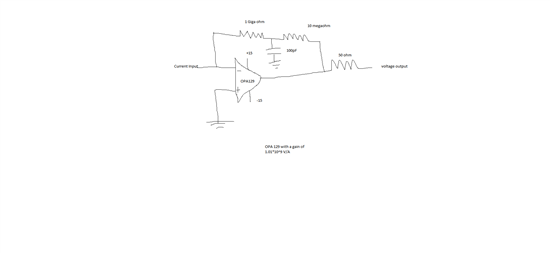
  • I have attached the schematic of the opamp circuit.

    The current input to this opamp is from an electrospray ion mobility spectrometer. ion mobility spectrometer has a column to ionize the liquid sample ,as the liquid passes through the column it gets ionized and hits a plate. This plate is connected to the opa129 input through a wire to amplify the current. As i have already said i am only getting a square wave for all the inputs and without any input also.

    please help me with this..

    thanks

  • Hello Deepak,

    The application you describe is not one that we typically come across, therefore we will try to provide some resources that may be of assistance.

    Blog series on transimpedance amplifiers:

    http://www.ti.com/hpa-pa-opamp-fb-thehub-20140516-20140507-part1-en

    Application note about compensating transimpedance amplifiers (TIA):

    http://www.ti.com/lit/an/sboa055a/sboa055a.pdf

    I also found this app note that uses the OPA128 in a TIA configuration:

    http://www.ti.com/lit/an/sboa061/sboa061.pdf

    Also, you may find the LMP7721 of particular interest. The maximum input bias current is just 20fA, which is less than the OPA129. Even though you've probably already read the OPA129 data sheet, the LMP7721 data sheet also has good information especially with respect to the PCB layout (e.g. guarding, shielding, and connectors). Finally, for such low-level current circuits it is extremely important to clean your PCB very well. Here is a good blog post that may be of interest:

    http://e2e.ti.com/blogs_/b/precisionhub/archive/2013/09/23/why-should-i-give-a-flux.aspx

    I hope this helps!

  • Deepak,

    The 100pF capacitance to ground in this circuit creates a serious stability problem and is certain to be related to the oscillations that you see. This capacitance should be eliminated. Use a single feedback resistor.

    Capacitance associated with your measurement cell is also problematic. Do you know the capacitance of your cell? You can experiment by adding a capacitor in parallel with the single feedback resistor. Try 20pF. This will likely stabilize the circuit.

    Regards,  Bruce