This thread has been locked.

If you have a related question, please click the "Ask a related question" button in the top right corner. The newly created question will be automatically linked to this question.

Amplitude Modulated waveform issue

Other Parts Discussed in Thread: MPY634

Dear Team,

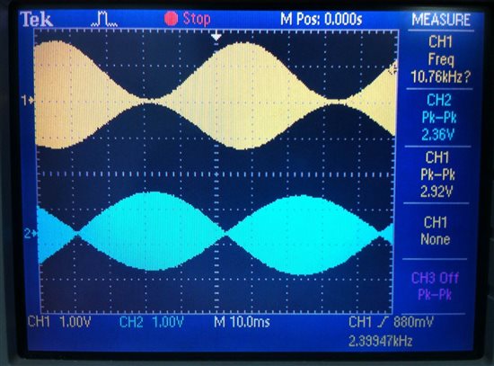
Please help me out to find out the difference between CH1 and CH2 waveform? Channel1 is a simulated Sin+ signal and CH2 is actual Sin+ signal from resolver, both are amplitude modulated. whenever I try to use simulated signal to drive motor, motor gets stalled. what could be major difference?


Regards,

Mala

  • Hello Mala,

    You didn't mention how you are generating the amplitude modulated (AM) signal so I will just concentrate on the two waveforms.

    Viewing channel 1 the lower frequency sine wave is clearly seen modulating the carrier. The percentage modulation appears to be just under 100 % because the sine wave is complete with no evidence of clipping. The percent modulation is computed from:

    AM mod (%) = 100 % (Emax - Emin) / ( (Emax + Emin)

    Emax is the peak-to-peak maximum of AM envelope, while Emin is the peak-to-peak minimum of the envelope. You can see that as E min approaches 0, that the modulation approaches 100 %. I would estimate that the signal shown in channel 1 represents about 95 % amplitude modulation.

    Viewing channel 2 it appears that the signal is highly over modulated. If the intention was to preserve a sine wave modulated waveform then that isn't the case. The over modulation is so extreme that the lower half of the sine wave has been clipped off. You end up with something that appears more like a half wave rectified sine wave modulating the carrier. That results in extreme distortion and harmonic generation.

    I would expect the solution to make channel 2 to appear like channel 1 is to reduce the amplitude of the modulating signal until the percent modulation is 100 %, or a little less.

    Regards, Thomas

    PA - Linear Applications Engineering


  • Hi Thomas,

    Channel 1 amplitude modulated signal is generated by automatic gain control amplifier and Channel2 is output of resolver, when BDLC motor's shaft is coupled with DC motor and supplying DC motor with DC supply and

    DC motor is supplied with DC voltage and it drives the BLDC motor coupled to resolver, channel 2 is a output of resolver between Sin+ and Sin-.

    I had tried to generate amplitude modulated signal even with voltage controlled oscillator and amplitude modulators.

    what I need to do is to match automatic gain control amplifier output/VCO with AM to match with resolver outputs, so that BLDC motor can be rotated without resolver.  

    Regards,

    Mala


  • Hello Mala,

    An analog multiplier such as the MPY634 can be used to generate AM. Data sheet figure 9 shows the multiplier connection. It is straightforward method for generating AM:

    http://www.ti.com/lit/ds/symlink/mpy634.pdf

    We don't have any specific resolver products in our analog portfolio. When I searched the TI web site I did find a white paper on the subject of a resolver to digital application employing the C2000 micro. I don't know if the information in that paper is of use to you, but I am sending the link your way for your review:

    http://www.ti.com/lit/wp/spry212a/spry212a.pdf

    Regards, Thomas

    PA - Linear Applications Engineering