This thread has been locked.

If you have a related question, please click the "Ask a related question" button in the top right corner. The newly created question will be automatically linked to this question.

Need help converting Dual supply to single supply

Hello E2E,

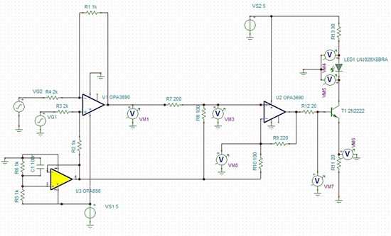
I am pretty new to design, currently building an LED modulator/driver that must be single supply. I had it working as a dual supply system before I found out it could only be powered by a single 5V rail. I have been taking a look at the material TI provides for Signle supply design, but the complex feedback i have ( the NPN transistor) seems to make it impossible to apply what they suggest.

The first Figure is the Dual supply system which has been functioning as desired( shown in the second figure). My attempt to convert it to single supply is the third figure, with the circled region posing the major problem, as the first section seems to be working fine. The problem as I see it is that the feedback section is now totally wrong, the inverting terminal does not follow the non-inverting input and the output of the second stage is also not reproducing a scaled version of the input.

If anyone has any advice on how to get this second stage working please let me know.

blake

opa3690, 16June 5Vsinglesupply diff+drive.TSC
  • Ive replied to this post to attach the second TINA design files.

    opa3690, 14June 12 dual supply.TSC
  • Hi Blake,

    It seems that the complex feedback being applied is not turning On the 2N2222 transistor due to which the loop is not completed and the result you are not getting the result. I have modified the circuit to accomodate simple feedback and it seems that the circuit works in single 5V supply. Please let me know if this is what you are looking for.

    Best Regards,

    Rohit3146.OPA3690_5V_LEDMod.TSC


  • Hi Blake,

     I notice several differences between the circuits for single and dual supply. I can work with you to help build up the circuit as we go along and you can tell me if the performance is as desired. I have noticed that your attached single supply simulation is different from your screen-shot.

    1. Supply Voltages - I notice that we have gone from +/-12V to +5V supplies. As a start, to ensure that we dont run into headroom problems I would change the single supply circuit to +10V. We can come back later and drop this back to 5V if needed, but as a start lets go with +10V.

    2. U1 Stage - This stage looks well designed and will convert your differential input signal to single ended with a transfer function of 1/2*(VG1-VG2). Can you please let me know what the previous stage driving this stage is? If the previous stage is a fully differential amplifier (FDA), we could adjust its common-mode voltage based on whether we are using a Single or Dual Supply circuit.

    3. Intermediate Stage between U1 & U2 - For the Dual supply circuit, you seem to have a resistive divider network to set the dc bias point and then an attenuator stage. I wonder if this circuit could be made simpler as shown in the attached simulation. Please let me know.

    7266.DualSupply_InterStage.TSC

    4. U2 Stage - Single Supply: Here I think we can make the circuit to have a similar transfer function to your dual supply circuit, wherein you use U2 as a VtoI converter with the help of the 20Ohm R11 resistor. To better help with this can you please let me know if the inputs will always be on a 0V common mode AND what the max input signal value can be.

    Samir