This thread has been locked.

If you have a related question, please click the "Ask a related question" button in the top right corner. The newly created question will be automatically linked to this question.

Recommendations and advice for my design

Other Parts Discussed in Thread: PGA281, PGA112, PGA113, LMP8358

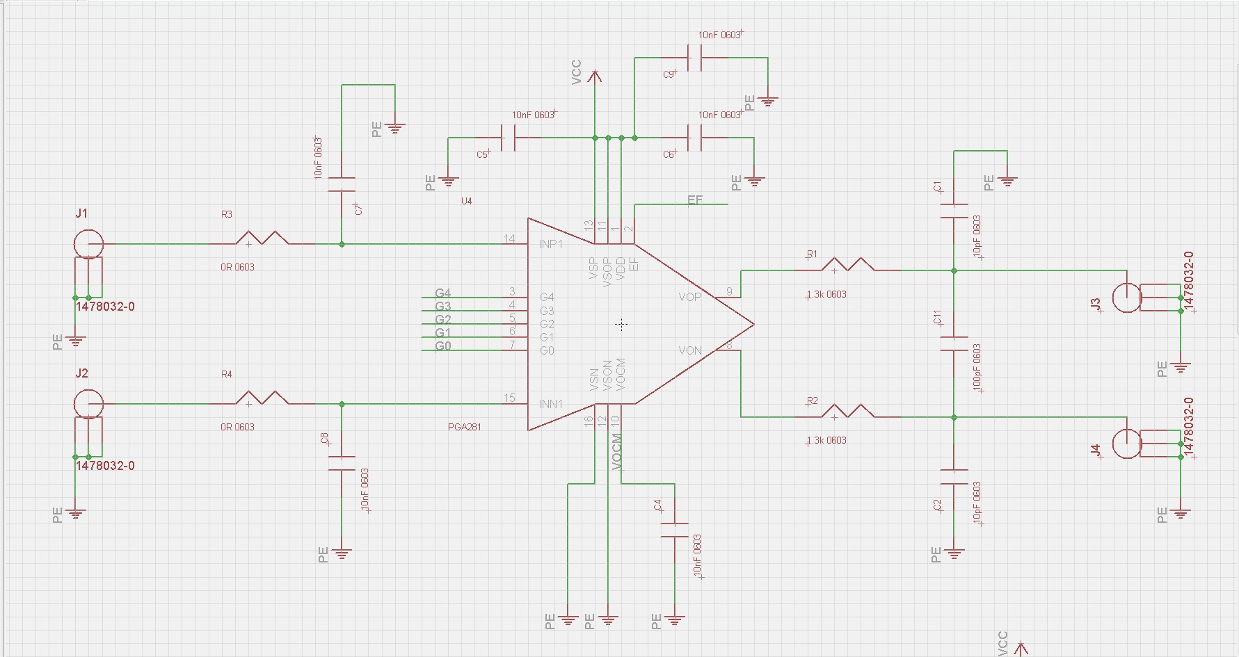
I'm trying to implement a very simple programmable gain amp requiring a minimum of passives.  I've found the PGA281 and it looks like the smallest chip I can get away with.  I'm an embedded/digital designer and don't have as much experience with filtering so I was wondering if some of you could look at these schematics and make recommendations regarding any improvements or any parts I could get rid   of.


The specs I'm looking for are a programmable gain amp that can take a differential input and produce a single ended output.  With this part, the data sheet says I can just pull off the positive output and that could be my single ended signal.  The only note is that the output will be half the expected magnitude since I'm only using 1 of the differential outputs. 


My application is to amplify sensor out puts that will be fed into an A/D convertor on a tiva c part.  I've attached the schematics below.  Any advice comments?
  • Hi Robbie,

    There's a TI Precision Design using the PGA281 (http://www.ti.com/lit/ug/tidu033/tidu033.pdf) which provides equations for computing filter components, based on your desired cutoff frequency. However, I can give you some typical values which work well to reduce broadband noise at the input of the PGA281. These values set a 10.1kHz differential filter and a 212.21kHz common-mode filter.

    • R3 = R4 = 75Ω
    • C7 = C8 = 10nF (already set)
    • CCM = 100nF (place across INP1 and INN1)

    If you're going to ignore VON, the inverting output, you can scrap R2, C2, and C11.

    Your values of R1 = 1.3k and C1 = 10pF set a very high output filter frequency. I'd recommend switching C1 for a 0.01uF (10nF) cap in order to set a cutoff of 12.2 kHz.

    Also, your power supply scheme will not work as-is. Please make the following corrections:

    • VSP and VSN are the high-voltage input supply rails. The minimum voltage at these rails is ±5V, but is typically ±12V or higher. 
    • VSOP and VSON are the output supply rails. VSON is typically 0V in order to interface with single-supply ADCs, but VSOP must be at least 1.5V less than VSP.
    • DVDD must be 2.7V to 5.5V, relative to VSON.
    • VOCM sets the output common-mode voltage. It's recommended that VOCM = (VSOP/2) in order to interface properly with single-supply ADCs and meet the PGA281 output common-mode voltage requirements. If you connect VOCM to GND as in your current schematic, you will violate the minimum output voltage of 0.1V and will not be able to accept negative inputs.

    Best regards,

    Ian Williams
    Linear Applications Engineer
    Precision Analog - Op Amps

  • Ian, Thanks for the reply! The 5 volt min. Requirement is a problem. For me. I have a product that only has a 3.3v power rail. Do you know of a part similar to this but can run completely off of 3.3v? All I need is a very simple pga. From your response I feel like this part will not be a possibility anymore because of the van and vsp.
  • Hi Robbie,

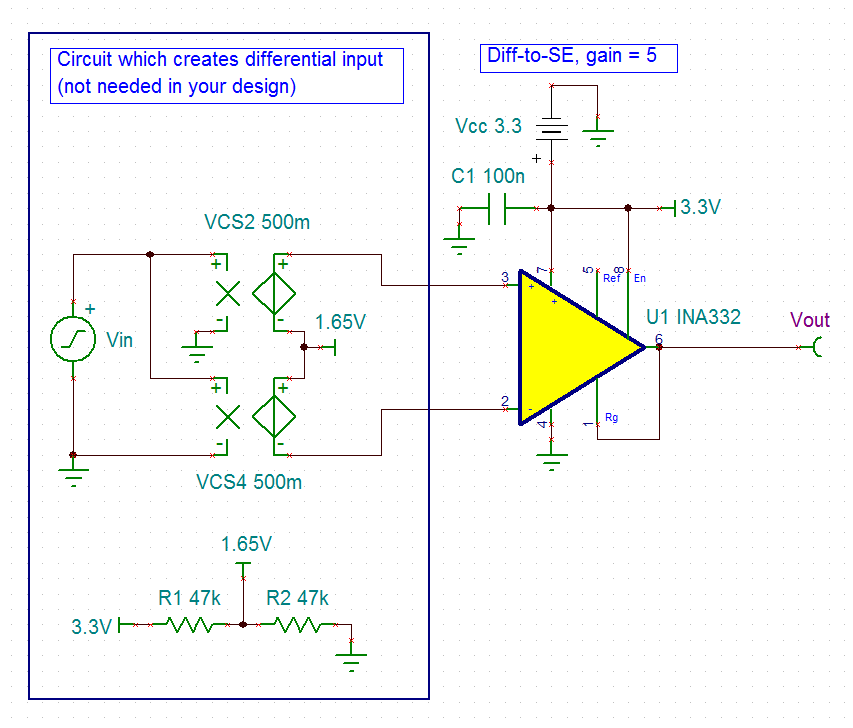
    Unfortunately we don't offer a similar device that operates on 3.3V power. However, the PGA112 (gain = 1, 2, 4, 8, 16, 32, 64, 128) and PGA113 (gain = 1, 2, 5, 10, 20, 50, 100, 200) may be of interest to you. These are both single-ended input devices, but a simple instrumentation amplifier circuit at the front-end will easily convert your differential signal to single-ended. I've attached a circuit in TINA which demonstrates this.

    The attached circuit provides a differential input with a common-mode of 1.65V, or Vcc/2. This is recommended in order to ensure that the amplifier's linear input and output voltage range is maintained. What's the common-mode voltage of the input in your system?

    Best regards,

    Ian Williams

    INA332 Diff. to SE.TSC
  • I'm not 100% sure if this is what you're looking for with the question of "what is the common-mode voltage of the input in your system", but any differential sensor I have attached should sit unstimulated at 3.3/2 or 1.65 like you used in your example above.

    Another thing that is making this more challenging is that I don't have any SPI ports left so I would need a digitally controlled (discrete) input to the PGA.  I am fine with using a plain old differential op amp to convert the signal.  I'm really just stuck on this PGA problem.  I've got the low pass filter going and the differential amp is no problem really because it shouldn't take up too much space using 4x of them with some passives.  The PGA has to be able to boost my sensor signal so if the sensor outputs a max signal of 50 mV (as an example) I may need to apply a gain of say 20 or something to increase it allowing me to get better data from my ADC.  I've found some parts elsewhere that almost do exactly what I'm looking for.  I know this isn't a TI part, but the LTC6910 would work really well except that it is an inverting amp.  I think being an inverting amp I would get no signal out because I have no V- (it would be grounded).  Do you guys have anything like this that would just apply a positive gain and pass my signal through?  Does that make sense?

    Thanks for the help!

    Rob

  • Hi Rob,

    Your understanding of the common-mode is correct. It's the average value of the differential input signal, or the DC value of each input pin when there is no stimulus. Keeping this at Vcc/2 or 1.65V is ideal.

    I understand your need for a pin-programmable PGA. The LTC device is not a TI offering, but we do have the LMP8358 which would work well for you. Here are the key features of the LMP8358:

    • Supply voltage from +2.7V to +5.5V
    • Gain of 10, 20, 50, 100, 200, 500, 1000 (non-inverting)
    • Pin-programmable or SPI-programmable gain
    • Differential input, single-ended output
    • Excellent gain accuracy, common-mode noise rejection, and offset performance

    Best regards,

    Ian Williams