A related question is a question created from another question. When the related question is created, it will be automatically linked to the original question.
If you have a related question, please click the "Ask a related question" button in the top right corner. The newly created question will be automatically linked to this question.
Your OPA381 output is clearly driven to its positve rail: (V+)-500mV. Does your simulation shows 2.8V output voltage or do you measure it in an actual application?
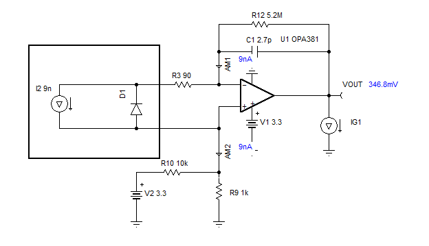
If you simulate the circuit, do you run DC sweep or transient analysis; if you use transient analysis, please make sure your I2 photodiode current of 9nA, does not change with time. I have simulated your simplified circuit and obtained expected result (Vout=~347mV); please see below and attached Tina-TI schematic.
If you built the circuit, what kind of PCB do you use? Is it possible that it has significant current leakages? Also, please check the output with a scope for any sign of instability.