This thread has been locked.

If you have a related question, please click the "Ask a related question" button in the top right corner. The newly created question will be automatically linked to this question.

INA129 output problem on unbalanced supply

Other Parts Discussed in Thread: INA129

Hello,

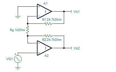
I am using INA129 with unbalanced supply (-V) is -2.5 and (+V) 11.5. The gain of the Differential amplifier is 50 but i am not getting the linear output after the output reach to +2.5 volt. i have applied 0 to 100 mVolt  in +Vin and 0 Volt in -Vin input signal and i got 14.5 m Volt to 2.80 Volt output, what is wrong in My case??

  • Harish,

    The internal op amp, A1, is limiting the positive-going output voltage. A positive input on the non-inverting input causes a negative-going output of A2 (an internal circuit node). This node reaches its maximum negative-going limit when the output of A3 reaches 2.5V.

    The positive-going output voltage swing can be improved by increasing the negative power supply voltage. Increasing the negative supply voltage by 1V (making it -3.5V) will increase the positive-going output voltage by approximately 2V (making the new maximum output 4.5V).

    Thanks for moving your blog comment to this forum and I hope this answer is clear and helpful.

    Regards-- Bruce.

  • Thanks Bruce ..

    Can you explain me in detail what it is how it works.....

  • Harish,

    The action of the two input op amps, A1 and A2 of the INA129 can be tricky to explain intuitively. I'll attempt a short explanation of the specific situation you are encountering. My explanation relies on a good understanding of the basic operation op amps:

    The positive-going voltage is applied to A2. Feedback of A2 causes the lower end of Rg to follow (equal) the input voltage. A1 behave as a simple inverter. The output of A1 is an inverted signal of the input with a gain of -24.5 (assuming perfect G=50 resistor values). So the output of A1 will go negative (with gain) with an increasing voltage input on A1. The output of A1 will reach its maximum negative output (limited by the small negative supply voltage) with a relatively small positive input voltage.

    Regards--  Bruce

  • Thanks  Bruce..

    i understood, i also find a good explanation of that on blow link

    http://masteringelectronicsdesign.com/how-to-derive-the-instrumentation-amplifier-transfer-function/