


Hi
i have seen this circuit in power supply product
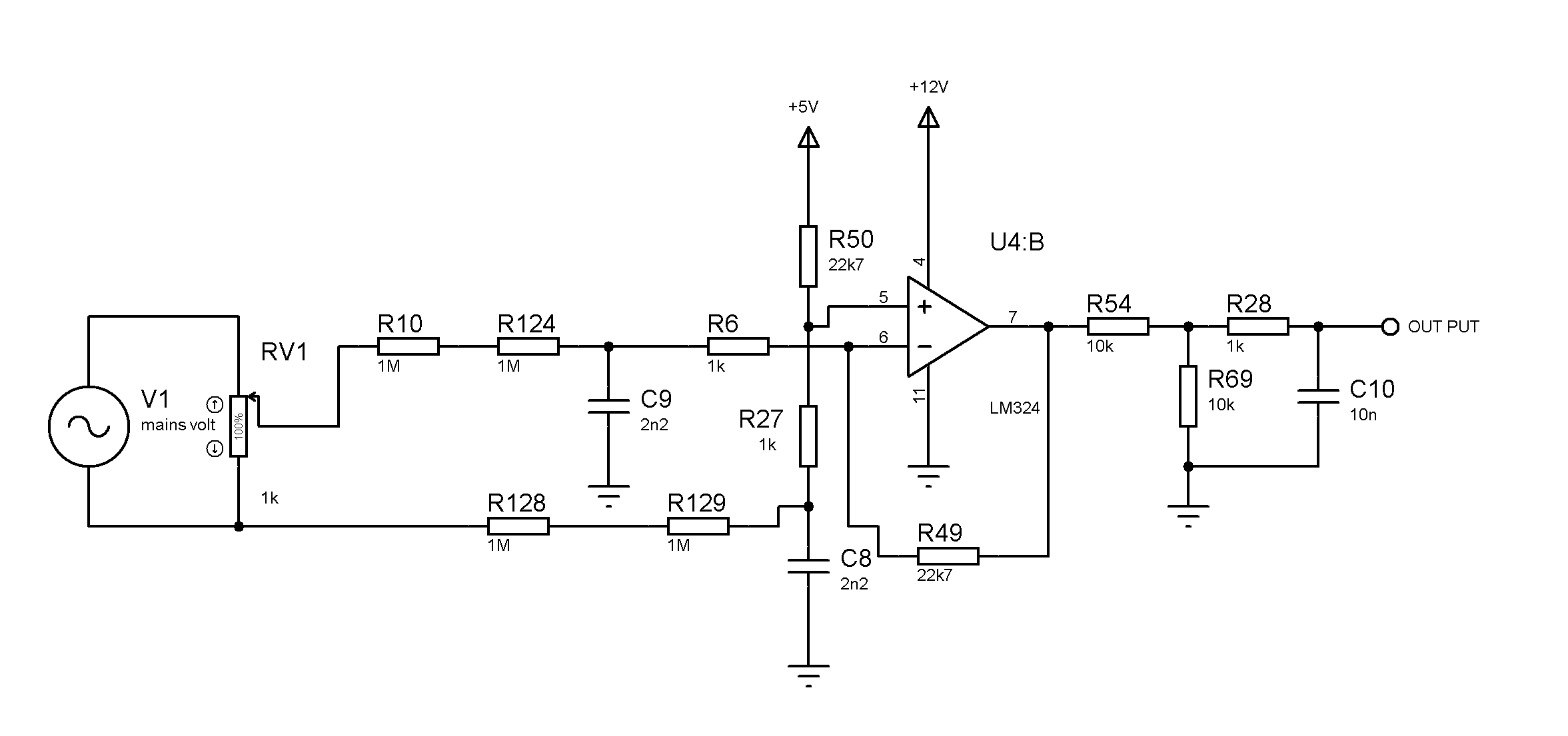
now in this circuit V1 and RV1 is just for simulation testing and actual mains input goes to R10 and R128 resistors
if i tries to change C8 and C9 values to 1nf then this circuit does not work properly
in this circuit changing various manufacturers LM324 ic gives strange (improper functioning) results
i am trying to build analog front end for micro-controller adc input stage for true rms volt reading
where my objective is to provide circuit isolation from mains by adding high value resistor to input stage and very low phase lag of mains signal should be appear on amplifier output
i have these question in this diagram
- what is the impact of C8 and C9 value
- why there is 1k (R27 ,R6 ) resistor to opamp input stage and what is importance for these resistors
- how to calculate R50 and R49 for desired output amplitude
so plz guide me
Regards
