This thread has been locked.

If you have a related question, please click the "Ask a related question" button in the top right corner. The newly created question will be automatically linked to this question.

XTR111 heating issues

Other Parts Discussed in Thread: XTR111

Sir,

I am creating a Highly Accurate Constant Current Source for LED using REF5025I as a voltage reference that will provide me a constant voltage of 2.5V and connecting its ouput to the input of XTR111 to convert it into a constant current of 25mA (Rset= 1K) 

My problem is that my XTR111 is getting very hot. A capacitor of 470 nF and two resistances(5.6K,8.2K) are connected across REGF and REGS pins. A mosfet BSP170P is also connected in the external current limiting circuit as shown in the datasheet application note.

Instead of these precautions,the IC is getting really very hot.What can be the reason for this and how can I rectify it so as to let my LED glow?

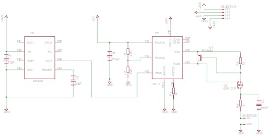
I have attached a bmp image of my schematic.

Thank you in advance

  • Hi Pratik,

    In your circuit R3 and R5 need to be 15 Ohms, not 15 kOhms.  What output current is the XTR111 delivering to the load while it is heating?

    Do you have any loading on the +5V output of the VREG?

  • Hello sir,

    Thank you!

    I have rectified the resistance values.

    The heating has reduced. It is showing 0 A output current.I too think there is some problem in the 5V regulator output since it not drawing any current.

    Can you please help me  so as to rectify this issue?

    Thank you.

  • Sir,  the XTR111 is drawing 21mA on 24 V power supply.

  • Hi Pratik,

    I didn't notice the first time I looked at the schematic but the REF5025 output does not have the proper output capacitance and as a result the output voltage could be oscillating which would explain the large current consumption of the XTR111. Please read the "Basic Connections" section of the REF5025 datasheet which I've copied below:


    If placing a proper capacitor on the REF output does not solve this issue, please clarify a few things which will help me understand what's going on.

    1.)  What is the VREG output voltage? 

    2.)  What is the VREG output current?

    3.)  What is the output current delivered to the load?

    4.)  What is the load resistance?

    5.) What is the supply current going into the V+ terminal?

  • Sir,

    Since the ESR value of output capacitor of  5025I IC should be Less than or equal to 1.5 ohms,I checked on internet and they said for ESR to be less than or equal to 1.5 ohms,value of capacitor should be 22 micro F. I used 20 micro F capacitor but the heating continued.

    I removed my XTR111 from circuit and checked the output value of REF5025I and it is properly giving me the expected constant voltage, but just when I connect my XTR111 in the circuit, all the values like VREG current and voltage become zero, output current to the load becomes zero.

    The supple voltages are as follows :

    24 V supply for XTR111

    5 V supply for Voltage regulator of XTR111

    and, 3.3 V supply for REF5025I

    Sir, I am trying to get a constant current output on this circuit, I am in  very much need of your help to find what is wrong with the circuit.

    Thank you in advance!

  • Hello Sir,

    I placed a resistor of 10K between Vout of REF5025 and Vin of XTR111 and then shorted it with a small wire due to which somehow some important  things got rectified.

    1. The heating has reduced to a high extent

    2. The voltage regulator was not drawing any current,but now it is drawing 8 mA of current which is close to desired.

    3. The reference IC5025 is now showing a proper constant voltage of 2.5V even when the XTR111  is connected :-) but the problem is that it is drawing a lot of power (i gave 3.3 V and it is drawing 20 V)

  • Hi Pratik,

    Unfortunately the information you've provided does not make sense.  Placing a 10k resistor and shorting it with a wire is the same as just having a wire. 

    Are you forcing +5V on the REGF pin, or are you measuring the output?  It was not easy to discern from your reply. 

    You mention the REG output is drawing 8mA, why?  What is it connected to? 

    What is the supply current of the REF5025?  Is it 20mA?  You mention 3.3V and 20V??

    Many of my questions may be resolved if you would simply share your PCB design and full schematic with us.  Can you send it to us? 


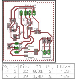
  • Ok Sir, I have inserted the Schematic and Board in this reply.

  • In the board, There is a four pin connector used for power supply.

    The first one from left is for 24V power supply for XTR111, the second for Ground, the third one is of 5V as power supply for Voltage Regulator of XTR111 and the fourth from left i.e. the last one is of 3.3V for Voltage Reference REF5025I.

    I am giving 3.3V to REF5025 because the datasheet had suggested that the power supply should be between 2.7 to 18V.

    At the bottom, The two pin connector is for my LED for using as a constant light source.

    Sir, after analyzing the board and schematic, what all problems and errors can you see in this idea?

    Thank you again!

  • Sir, IF this doesnt work, What would be your opinion about using an Evaluation board of XTR111 i.e. XTR111 EVM for getting a constant current output?

     Thank you!

  • Hi Pratik,

    It looks like the PCB footprint you used for the XTR111 did not include the required PowerPAD connection to GND on the bottom of the IC.  The PowerPAD is shown in Figure 5 and the PCB layout requirements are described on page 21 of the datasheet. The device will not be able to properly dissipate power if the PowerPAD is left unconnected, explaining the heating issues you're experiencing. 

    If you look at the PCB layout for the XTR111EVM you will see that the PowerPAD is included and properly connected to GND. 

    Please let us know if you have any additional questions.