This thread has been locked.

If you have a related question, please click the "Ask a related question" button in the top right corner. The newly created question will be automatically linked to this question.

XTR300 value of RGAIN

Other Parts Discussed in Thread: XTR300

Dear Community

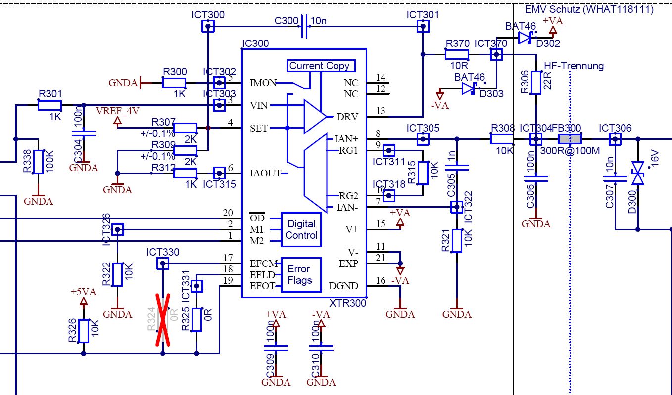
We use the XTR300 as Voltage or Current Output Driver (+/-10V or +/-20mA) in a Standard configuration (Rset = 2k, Ros = 2k, Rgain = 10k).

Because of some heat Problems, I'm trying to reduce the power Dissipation of the device. One Point is the current consumption of the IA, which can be reduced by rising Rgain. But all the electrical characteristics in the datasheet are specified with Rgain = 10k. What could be the consequences if I rise Rgain to 20k? Are there any documents available concerning this point?

Best Regards

Martin

  • Hello Martin,

    Increasing RGain will decrease the output current of the IA which will reduce the power consumption slightly.  Likely most of the power dissipation is coming from the output circuitry.

    While the AC specifications of the XTR300 were taken with a 10k RGain resistor, the DC parameters were recorded with a 2k RGain resistor.  I guess my point is that the device was not intended to be used with only a 10k Rgain resistor and doubling the value to 20k should not noticeably impact performance.  Unfortunately we do not have any documents or characterization results in this configuration.

    Would you like me to review your schematic? Should you experience issues with the 20k resistor, contact us back with the results and we'll try to resolve them. 

  • Hello Collin

    Thanks for your answer. I've tried the configuration Rgain = 18k, Rset = 3k6 and Ros = 3k6.
    As you said, there is no major impact to the output signal, the output slew rate is a bit slower but this shouldn’t be a problem for our application.

    With two output channels, the current consumption is reduced by 7mA which results in a 120mW (ca. 10%) lower power dissipation.
    It’s also possible use Rgain = 100k, Rset = 20k and Ros = 20k, but the Output slew rate gets really slow (around 1.5ms 10% to 90%).


    The output driver is wired as follows:

    Regards

    Martin

  • Hi Martin,


    Thanks for the information. It sounds like the application is working well.  Unfortunately, the image you attached did not get uploaded correctly.  Would you please try uploading it as a file instead of as an image?

  • Hi Collin

    Here's another try to post the schematic:

    By using Rgain = 28k (56k//56k), Rset = 5k6 and Ros = 5k6, I still get a sufficient rise/fall - time and can reduce the power consumption for the whole device by 200mW (with isolated dcdc-converter). This should work for our requirements.

    Regards
    Martin 

  • Hi Martin,

    Thanks for sharing your results and good news that the circuit is meeting your requirements. I reviewed the connections on your schematic and everything seems to be in place.  Be sure to place the decoupling capacitors on V+ and V- close to the IC for proper decoupling.