This thread has been locked.

If you have a related question, please click the "Ask a related question" button in the top right corner. The newly created question will be automatically linked to this question.

Current requirement for LMH6554

Other Parts Discussed in Thread: ADC12D1000, LMH6554, TINA-TI

Hi,

I am using 4 numbers of LMH6554 devices in my designs for single ended to differential input to ADC12D1000.

I am providing VCC=+2.5V and VEE=-2.5V.

I am using TPS7A4701 and TPS7A3301 to generate  VCC and VEE respectively.

These regulators source 1A each.

In the device datasheet I found the two types of currents.

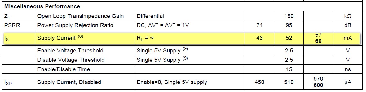
IOUT=150mA and ISS=60mA.

For the power calculation or for the selection of regulator, which current I need to consider?

I need the information to consider the total power requirement by the card.

Please help me on this.

Regards,

Amit K Bhat

  • Hello Amith,

    For each LMH6554 stage, this is the supply current information to consider, about 57mA Max room temperature supply current:

    This is the quiescent current draw of the LMH6554. If the load current is significant, you may have to consider its contribution as well. That would be dictated by the output voltage and your load impedance.

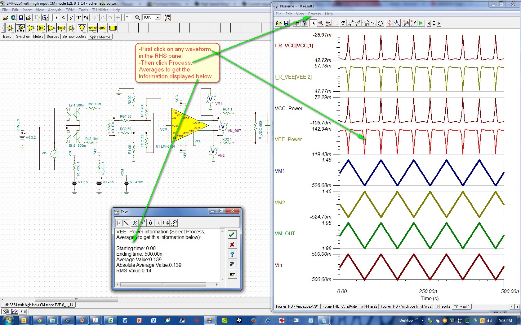
    You can also use TINA-TI to compute typical power dissipation as well, as shown below. I've created the VCC_Power and VEE_Power functions here and I find their RMS values using TINA-TI (this includes device quiescent power dissipation as well as the load power):

    Here is the TINA-TI file I've created / used for this purpose:

    6215.LMH6554 Power Computation E2E Hooman 8_19_14.TSC

    For the "Power" waveforms, in TINA-TI waveform display panel, you could select Process, Averages and the RMS and average information is displayed. Here is what I get with this circuit from performing Averages inside TINA-TI:

    VCC_Power:

    Average Value:-0.102
    Absolute Average Value:0.102
    RMS Value:0.102

    VEE_Power:

    Average Value:0.139
    Absolute Average Value:0.139
    RMS Value:0.14

    Total Power = 0.102W (for Vcc) + 0.14W (for Vee) = 0.242 Watt

    Regards,

    Hooman

  • Hi Hooman,

    Thank you for your reply.

    As of now I have considered the maximum current consumption by the device as 60mA for power calculation.

    You have mentioned that  "If the load current is significant, you may have to consider its contribution as well."

    I am driving the differential data to ADC and the load impedance is 100 Ohm differential with pk-pk 800mV max.

    What will be the safest source current to the device, considering the load?

    Please let me know whether the current consumption by the device will exceed 100mA if we consider the load?

    Please help me out.

    Regards,

    Amit K Bhat


  • Hi Amith,

    It is fairly straight forward to account for the contribution of the "load" to the power supply current.

    Take your example:

    Differential load: 0.8Vpp across the 100ohm of the ADC input impedance. That amounts to 4mA (=0.4Vp / 100ohm) load-related supply current from both V+ and V- supplies. So, in this case the load current is fairly insignificant compared to the quiescent current(s).

    CM Load (if any): If you LMH6554 output pin(s) were CM loaded, if you wanted to account for everything, you would also have to consider the effect of that on supply current. Say for example, your output is 1.2V V CM and both outputs have 1kohm to ground loading. Then only the V+ supply LDO will need to supply an additional 2.4mA (= 2 x 1.2V / 1kohm) for CM loading of both outputs.

    Something about the LMH6554 TINA-TI model:

    Earlier I had implied that the model predicts the supply current (V+ and V-) including the contribution from the load. I've since found that the TINA-TI model only accounts for the quiescent current and does not include the load current! So, please keep that in mind if you ever go the simulation route.

    Capacitive Load @ high frequency: A subtle supply current component is from the voltage swing across the ADC input capacitance. In the simulation below, I've found that it is about 3.4mA from both the V+ and the V- supply (0.8Vpp swing across 2pF ADC input at 700MHz). This is additional current that the LDO's / regulators much supply. I've used an Ammeter (I_C_load) in my TINA-TI file to show the ADC input capacitance transient current:

    Here is the TINA-TI file associated with the simulation above:

    6758.LMH6554 Power Computation E2E Hooman 8_19_14 Revised 8_20_14.TSC

    Regards,

    Hooman

  • Hi Hooman,

    Thank you for your reply.

    If I consider the Load current in my case, the regulators have the capacity to supply it with good margin.

    Thanks again for your support.

    Regards,

    Amit K Bhat