This thread has been locked.

If you have a related question, please click the "Ask a related question" button in the top right corner. The newly created question will be automatically linked to this question.

INA132 resistor matching

Other Parts Discussed in Thread: INA132, TINA-TI

In the INA132 spec, it says "do not interchange pins 1 and 3 or pins 2 and 5..."    How should I interpret this?  Can I rely on R1 and R2 to give me a gain very close to -1?  Can I tie pins 1 and 3 together to give a noninverting input?  Thanks.

  • Gene,

    Swapping pin 1 and 3 or pins 2 and 5 in INA132 might potentially not just result in changing the polarity of the gain error BUT even more importantly since common-mode rejection ratio relies on matching the gains (and errors) in each of the two resistor networks, doing so would result in a significant deterioration in the CMRR specification (CMRR spec would not meet the PDS limit).


  • I need the answers to my other questions.  I am running out of time.  Should I call tech support?

    I understand that you don't want me to swap pins.  But I would like to know how the resistors can vary.  Can I get that information?

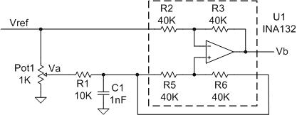
  • Here is a more detailed look at my application:

    Will the INA132 give me a precise, stable gain of -1 to the R2 input, and a precise, stable gain of +2 to the R5/R6 input?  Maybe it would help if you called me about this.  My email address and phone number are in the TI database.

  • Gene,

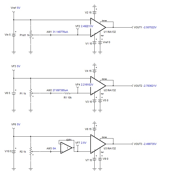
    INA132 is a difference and not instrumentation amplifier so there is a relatively large input current flowing into the input terminals.  For that reason any resistor in series with the either input will cause an error.  In the first case (see below), AM1 current flowing thru upper but not the lower portion of potentiometer will cause an error.  In the second case, adding 10K resistor will make the error even greater as AM2 current will cause additional voltage drop across R1.  Thus, to eliminate the error associated with the input current, you must buffer the input as shown in last circuit below so that input current AM3=0.

    Attached please find the Tina-TI circuit you may use for your simulation.  You may dowload free Tina-TI software by clicking on the link below:  http://www.ti.com/tool/tina-ti?keyMatch=tina-ti&tisearch=Search-EN


    INA132 circuit.TSC