This thread has been locked.

If you have a related question, please click the "Ask a related question" button in the top right corner. The newly created question will be automatically linked to this question.

startup current for INA21X

Other Parts Discussed in Thread: INA213, TIPD135, TIPD104, INA129


Hi

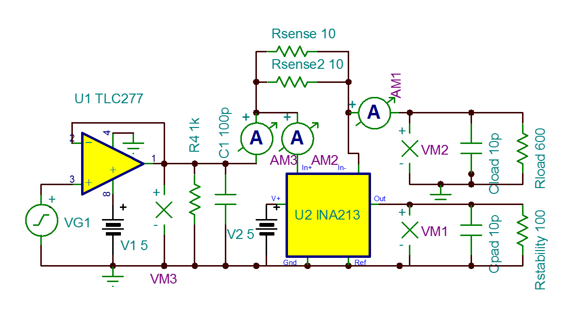
I would like to use the INA21X family for current sensing of about 5mA (load of 600ohm with supply of 3V)

for this reason I am using a series resistor of 10ohm in the input of INA213.

On transient simulation, when using a step response of the 3V supply, I see that for a short time, the INA213 takes about 1mA of current like so:

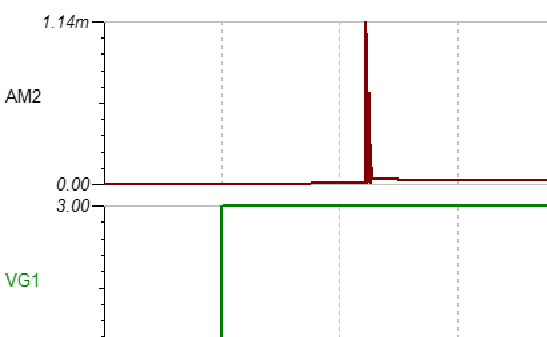
Is that normal? How can I reduce this current?


Thanks, Noam Kaminski


  • Noam,

    I have a few questions -

    1. How accurately are you trying to measure that 5mA?  Will you be measuring varying amounts of current between 0 and 5mA, or just simply 0 and 5mA?

    2. Could you attach the simulation file you are using and not just the screenshots?  I would like to play with your model myself and see what kind of timing that pulse has and where it occurs.

    3. Suppose the current is present exactly as shown in the simulation - is that a problem in your system?  If it is, what would be an acceptable level of overshoot, if any?  Does it matter if there is transient overshoot on the IN+ line if OUT is unaffected?

    Typically these current shunt monitor products are intended for larger currents and don't work as well with large shunt resistors and small currents.  There are a few TI Designs that use instrumentation amplifiers and PGAs to measure small currents, check out TIPD135 for sure and possibly TIPD104.

    The front end circuitry is not the same as a true instrumentation amplifier; it is tailored to work with small shunts (mOhms) and large common mode voltages.  It may be that what you're seeing in the simulation is an artifact created by that circuitry and a steep change in common mode, though I can't be sure at this moment.

    What is the target application for this circuit?

    Thanks!

    Jason Bridgmon

  • Hi Jason

    Thanks for your reply.

    1. I need to measure 4.5mA - 5.5mA, with rather low accuracy of 0.1mA.  BUT - I do not think that this is the issue here, because I ahve another circuit to measure 0.6mA with different INA21X and I see the same problem.

    2. Here is the simulation file

    3005.TLC277_and_INA210.TSC

    I also "played" with it. I think that the timing is not the case here - I see the current spike whenever the common mode voltage to the INA21X gets to about 2.2V.

    3. Normaly I do not care about it. But the output is affected to some extent and on the output I have a device which is sensitive to ESD, so I am afraid.

    4. As for TIPD135 - it has a differential output that I can not use and also needs +-15V supply that I don't have, so I am using the INA21X

    5. As for simulation artifact - I also had a talk with Kirk Milling, who supports IBM, and he had the same idea.

    6. The application - This circuit is meant to be on a test board with a socket for other devices.


    Thanks again, Noam.

  • Noam,

    Reviewing the INA213 data sheet, figure 11 on page 9 shows how at a common mode change of about 2.4-2.5 volts, the input bias current jumps up about 10x, from 2uA to 20uA.  I set up a circuit similar to your simulation in the lab but I shorted VIN+ and VIN- together, and I put an true instrumentation amplifier based current shunt solution (with an INA129) and observed the waveform as I made the transition across that 2.5V threshold.

    I did see the current increase as shown in the data sheet, figure 11, but I did not see the 1mA spike or resultant ringing that shows up in the model.  It was a nice, rounded off curve which flattened out.  I also didn't see any motion on the OUT line, which was resting roughly at 0V, as expected.

    I hope that helps,

    Jason Bridgmon