This thread has been locked.

If you have a related question, please click the "Ask a related question" button in the top right corner. The newly created question will be automatically linked to this question.

inverting op amp design

Other Parts Discussed in Thread: LM393

The image above is my schematic.  I want to invert the voltage VGL(which can be -7.7v to -6.3V) and use it to close a relay(RL6) if the voltage is within range.  Is the component IC10A correctly connected with the two feedback resistors R27 and R28 to invert the voltage?  I know the gain of IC10A should be -1 but when I connect up just the one LM393DR it does not invert the voltage at output pin 1.  Am I missing a pull-up resistor on pin 1?

Thanks,

Thomas Meiswinkel

  • Hi,

       I don't think you can have VGL between -7.7V and -6.3V as it will violate the common mode input voltage range of LM393.  

    Min value that VGL can take in your case is 0 V I guess. Check VICR (Min) (V) parameter given for LM393 in a tabular column in this link. http://www.ti.com/product/lm393 

  • Hi Deepak,

    Thanks for the quick response.  Is there an op amp that allows a negative voltage for the common mode input voltage range?

    Thanks,

    Tom

  • Hi,

    Try using the same LM393 op-amp in dual supply mode. Something like +12 and -12. In this case, the common mode voltage must not be less than -12 V. So  your VGL between -7.7V and -6.3V may probably work .

  • Hi Thomas,

    You can push a comparator in to an "op-amp like" operation. But it will be a VERY, VERY poor, slow (and messy) op-amp.

    You will need the pull-up resistor on 10A, as the output cannot swing high without it. It would not even work as a comparator!

    To make a comparator into an op-amp, you need a R-C network on the output. Remember that the comparator output is a two-state output (hi or low), so what you end up with is a pulse-width modulated "digital" output of pulses. The output R-C network integrates the PWM'ed pulses into a DC "output" voltage. If the cap is too large, the narrow pulses cannot charge it, and if it is too small, there is excessive ripple. Start with about 0.1uF with a series 1000 ohm resistor.

    This is described in section 21 (pg. 26) of Appnote AN-74 A Quad of Independently Functioning Comparators

    Also, because of the PWM'ing of the output with fast edge rates, supply bypassing and layout become critical. It becomes a high-frequency circuit an a potential source of noise.

    The inverting amplifier configuration can measure negative voltages as long as the input common mode voltage does not get violated. With a properly functioning op-amp, the negative input should be at the same potential as the positive input as long as the output is within it's linear range. So the positive input must be at or above ground.

    In the inverting configuration, the gain set resistor (R27) pulls current out of the feedback resistor (R28), and the output swings to maintain the zero balance at the inputs. Applying a negative voltage on the input would make the output go positive. This works up until the output hits the limit. A clamping diode should be applied to the negative input to make sure it is not pulled below ground if the output rails.

    The problem is that your "op amp" output may not have enough current drive to counteract the input voltage. So you would need to change R27 & R28 to much higher values - like 100K - to reduce the loading.

    So...stick a 10K pull-up resistor on the output, add a 0.1uF cap to the output, and change R26 and R27 to 100K and give it a try...but do not expect too much..

    Can you put the relay on the positive side? You are burning a lot of current in R25. Reverse the inputs of the A and B channels and put the relay where R25 is now. You are burning a lot of current in R25.

    There should also be a flyback diode across the relay coil, too.

    Regards,

  • Thomas,

    Skip the active voltage inverter. Instead make a simple two resistor voltage divider between VGL and 24V. 
    If both resistors were the same value then the voltage at the tap would be (VGL + 24V) / 2 which is in the valid common mode of IC5A and 5B. 

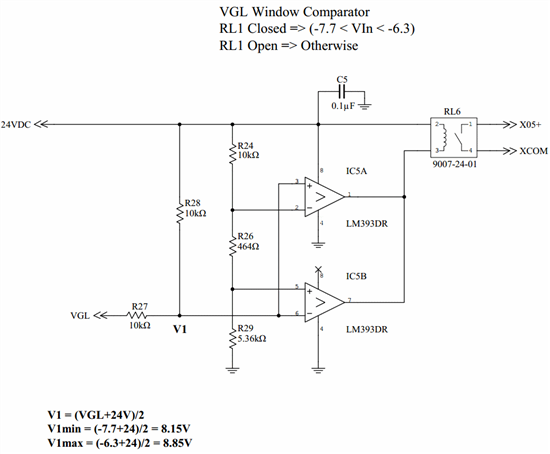
  • I setup a circuit with the voltage divider below.  This appears like it is the optimal solution since it eliminates an op amp.  Does this look okay?

    Thanks,

    Tom

  • Hi Thomas,

    I am still very concerned about the output. You are going to destroy the 393!

    When either output is "low", it will pull the 500 ohms to ground from 24V.

    24V/500ohm = 48mA through the output transistor when the relay is "off". Abs max on the output current is only 20mA.

    48mA*24V = 1.15Watts!!! You will overheat, and eventually destroy, the LM393, especially if it is in a package smaller than a DIP. R25 would need to be a minimum of 2 Watts. It's also a huge waste of power...

    The relay coil should be where R25 is. You will need to reverse the inputs on each comparator since the relay will be energized when either output is low. If you need a grounded relay then use an external high-side transistor/MOSFET.

    Relays are generally driven "high-side" (common positive line) to allow OR'ing and ease interfacing.

    Regards,

  • Hi Paul,

    Attached is my revised schematic with the relay shifted to the positive voltage source.  How does this look?

    Thanks,

    Tom

  • Hi Tim,

    Ah, I feel much better now...

    I assume by the part number, it is a Coto reed relay. That should be about 10-15mA, well below the max current.

    Don't forget the obligatory diode across the relay coil to clamp the inductive kickback, otherwise you may be occasionally replacing 393's. It may be built-into the relay, but I would still include it, or include a space for it in case someone "cost reduces" (or miss-orders) the relay with the built-in diode.

    Regards,

  • Tim,

    LM393 is certain to output 4mA, it'll likely do 10mA. Above that is very risky. Some may not have enough sink current.
    A small PNP like 2N3906 will greatly improve the drive. Base goes to LM393 outputs, emitter to relay and collector to ground. A 100k resistor from base to emitter will prevent off LM393 leakage from PNP turning on.

    A diode across relay is required.
     

  • Tim,

    Looking at original request "Relay on for in window". With tied outputs, the comparators only work when High for in window and Low for outside window. 

    So reverse the inputs back and use NPN to drive relay when both LM393 outputs are high. Base to LM393 outputs, emitter to ground and collector to relay. Add about 20k resistor from 24V line to base (1.2mA base drive).

  • Hi Ron,

    Thanks for the response and help on this circuit.  Attached is the revised schematic image.  How does this look?

    Thanks,

    Tom

  • Tom,

    It looks OK. Simulate it with minimum and maximum values for 24V line to be sure thresholds are still acceptable.