This thread has been locked.

If you have a related question, please click the "Ask a related question" button in the top right corner. The newly created question will be automatically linked to this question.

XTR116 and PIC16F877 PWM Connection

Other Parts Discussed in Thread: XTR117, XTR116, XTR111

Hi Everyone,

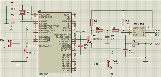
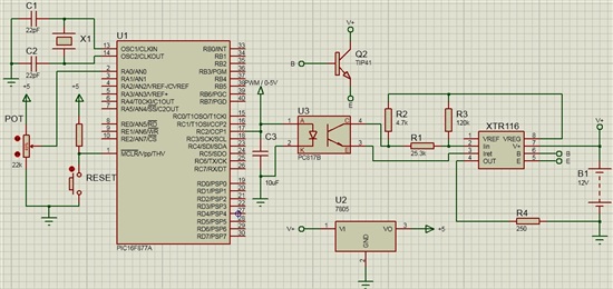
I did the conversion 0-5V 4-20ma convert with XTR 116. Circuit schema like in the photo. I want to use PIC16F877 instead of potentiometers. Using PWM want to get to 4-20. But I don't know how to make a connection. I would be glad if you can help. Thank u so much..
  • Hello,

    We can help you connect the MCU to the XTR11x devices for a PWM based current loop output.  However, because there are many nuances to 2-wire 4-20mA transmitters it would be great if you could share a rough block diagram of everything in your system so we can understand the power requirements from the "VREG" output of the XTR117. 

    Some main questions are:

    1.)  Does the MCU need to control more than 1 XTR?
    2.)  Does the MCU communicate with any devices that aren't powered between the XTR VREG and IRET signals? 
    3.)  Are there any isolation requirements for your system?

    Answering these questions will greatly help us put a solution together for you.

  • Hello Collin,

    Sorry for being late on this. 

    1) No I need to 1 MCU Control for 1 XTR116. I'm using control with PWM. (ADC)

    2) I used to PNP Transistor for MCU and XTR116 connection. I've only just pot normally use, without MCU. 

    3) I'm using the dc supply GND as isolation.

    To give a better idea I've shared in the circuit diagram(V+ = 12V). According to this diagram , Vreg output 5V supposed to be. But when I play with the pot is changing. I don't see 4.096V at pin Vref. I see higher. I see the V+ voltage at VREG pin. However, VREG pin is 5V regulator output. Why this is happening ?

    4-20 mA output I see when I play with the pot. But the response time is slow.

    Thank you very much for your answer and your help .

  • Hello!

    Thank you for sharing your schematic, it makes your system much easier to understand.

    First, there's a large issue with your schematic in that the GND symbol in your system doesn't appear to be connected to the IRET pin.  Consider the IRET pin the local GND for all circuitry powered from the VREG output.  This is shown in the applications section of the product datasheet. 

    It is also very important that you do not connect the IRET pin to the GND signal of the loop-supply / RTN as this will cause issues.  The IRET pin must float up and down as the output current changes the voltage through the load resistor. 

    If you're going to make measurements on circuitry powered between VREG and IRET, then you must use a floating meter (no hard GND connection) with the black terminal on IRET.   

    Second, for a low-side PWM circuit you should use an NMOS transistor with the emitter connected to IRET and the pull up connected as you currently have it.  You should use a larger value for R5 because another requirement of 2-wire transmitter loops is that the current drawn from VREG can't exceed ~3.5 mA or the transmitter will not be able to output 4mA properly.  With a 2.2k resistor to +5V you'll burn roughly 2.2mA which may not leave enough current to power the MCU.

  • Hi Collin,
    Thank u so much for answer.

    1) I feed system from a single source (Vloop). I did circuit isolation. But I'm using the ground of Vloop sources. So I'm using as of the system GND. Does theproblem ? Or how I'm gonna use ?

    2) What is the Black Terminal ? Sorry, I don't know.

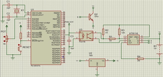
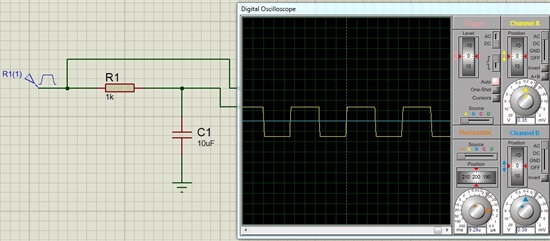
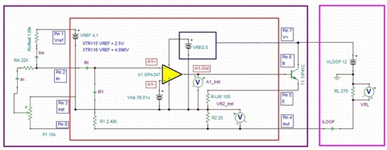
    3) I also like the second picture ,By taking the average of the PWM signal , R4 would like to see on the DC volts .To dothis, put your capacitor C3. Works is not it ? (PWM Frequency is 20Khz)

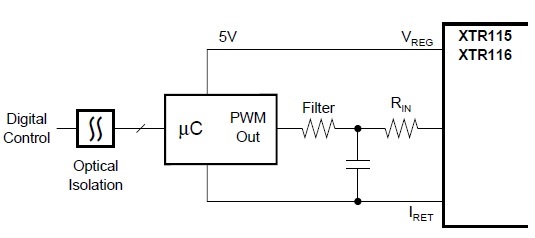
    4) After optocoupler amplifier circuit any required? In the third picture(in datasheet) shows,but I dont understand.Can you suggest a few optocouplers ? Finally, Can you tell me my mistakes in design ? :)


    It was a bit more questions :) Difficult for me, but easy for you :) Thank u so much for interest and answers.
    First Picture:


    Second Picture:


    Third Picture:


  • Hi Collin,

    I 've changed the circuit resistor values ​​. I implement on a breadboard . New circuit as follow.

    Load resistor values ​​over : 0V ---> 1.023V (Load resistor=250 Ohm)

                                                  5V ---> 5.07V   (Load resistor=250 Ohm)

    But responce time is slow of potantiometer. Also certain values ​​in the range of 1.023V . How do I make a full linear ?

    Thank u very much..

  • Hello,

    You need to modify your circuit to look more like the circuit in Figure 3 by adding an additional series resistor between the R2 pull-up and the R1 input resistor.  You'll also need to place a capacitor between IRET and the node between the new resistor and the R1 input resistor.  This will convert your PWM input to a dc voltage for the XTR input.

    We didn't discuss this earlier, but do you actually need a 2-wire transmitter or could your system use a 3-wire transmitter?  A 3-wire system is much easier to interface to a system with a local GND.  Take a look at the XTR111.  There won't be any grounding issues between the MCU and XTR111.

  • Ok. I'll additional series resistor between the R2 pull-up and the R1 input resistor. 

    I this design, I'm doing this for the measurement of the sensor . Otherwise I 'm gonna use XTR11 .

    ( http://www.melexis.com/Infrared-Thermometer-Sensors/Infrared-Thermometer-Sensors/MLX90614-615.aspx ) 

    Thank you for answer and interest.. Good works..