This thread has been locked.

If you have a related question, please click the "Ask a related question" button in the top right corner. The newly created question will be automatically linked to this question.

high frequency Op amp differentiator

Other Parts Discussed in Thread: OPA836, LMH6629, TINA-TI

Hi friends,  

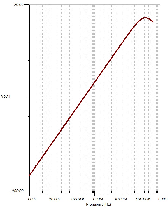
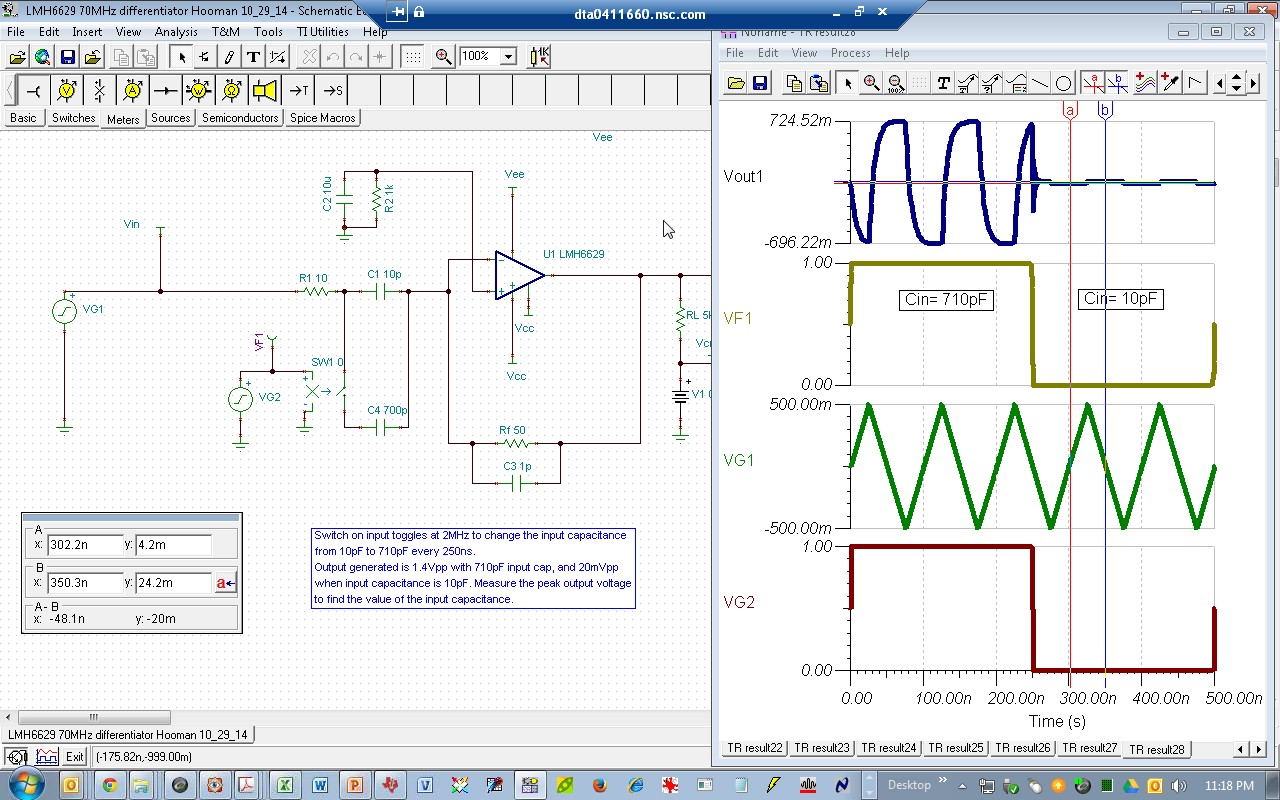
        I want to set up a differentiator circuit using op amp which work in the range of 70 Mhz . I am giving 70 Mhz unipolar triangular  wave as input. Can any one suggest some op amp which work in this frequency range? 

Thanks,

Tharanath

  • Hello, What power supply rails do you have for your circuit? The OPA836 could be a useful fit for low supply applications. You can use TINA Spice (available on the TI website) to simulate your circuit to ensure you are meeting required specs.

    Thanks,

    Samir

  • Hi Tharanath and Samir,

    In addition to the OPA836 that Samir has recommended, you can also consider a faster, lower noise device like the LMH6629. Here is a differentiator with 70MHz capability based on the LMH6629 (including components needed to make sure the circuit is stable):

    Here is the frequency response:

    TINA-TI file:

    1581.LMH6629 70MHz differentiator Hooman 10_28_14.TSC

    Regards,

    Hooman

  • Hi Sameer,

     I am so happy and thankful to you. Actually I am developing a system to measure capacitance by differentiator by applying triangular 70Mhz as input and measuring square wave out amplitude as out put. Right now I am using some built in ic for generating square wave for triangular generation ( Integration ). Is this right way to measure capacitance? Can you suggest some ideas? My requirement is that out vary from 0 to 3 voltage (square wave).

    Could you suggest some single supply op amp in 70Mhz range?

    Thanks,

    Tharanath

  • Hi  Hooman,

      I am so happy and thankful for your reply. I need a single supply op amp in 70Mhz range. Would you be kind enough to suggest some op amp in this range? Also 70Mhz triangular generation technique? Should I take care about stability of differentiator? My out put is square wave amplitude( whose out put is zero to 3 v). In this 0 to 3 v span i want to measure 100 readings. So differentiator should be capable of producing accurate voltage in its ON state.

    Please be kind enough to reply.

    Thanks,

    Tharanath 

  • Hi Hooman,

     I am very much excited to meet you. I am interested in writing transfer function of op amp circuit manually. Could you help me to write transfer function of your differentiator circuit ?

    Thanks,

    Tharanath 

  • Hi Hooman,

     would you be kind enough to explain practical  a differentiator in 70 Mhz range? I mean all considerations like stability and all?

    Thanks,

    Tharanath

  • Hi Tharanath,

    This link might explain some of the questions you had posed as to why differentiators are inherently unstable and how to make them stable:

    http://www.electronics-tutorials.ws/opamp/opamp_7.html


    Regards,

    Hooman

  • Hi Hooman,

        Thank you for your reply.I just want to measure capacitance in the range of .01nF to .71nF. So I need a differentiator circuit whose  out put varies with capacitance in the above said range. I need out varies in 0 to 3 v range according to the capacitance. Vout= Vin*RC/t  is the equation for differentiator.  

    If Vin=3V, f=70Mhz, C=.71nF(Max value), then R will be around 10. When i put all those value in the circuit you sent it show noise. And one more thing is that will thecircuit work if RC>t?

    Would you kind enough to help me?

    Thank you,

    Tharanath

  • Hi,

    Here is a circuit which produces 1.4Vpp with 710pF input cap, and 20mVpp with 10pF (ratio of caps matches the ratio of voltages to confirm operation). However, my input ramp is only 10MHz, not 70MHz. What's the reason that you need a 70MHz test signal, as that makes it more challenging?

    6761.LMH6629 70MHz differentiator Hooman 10_29_14.TSC

    Note that I'm using the TINA-TI switch on the input to conveniently switch the cap value and view results of the min / max cap value simultaneously to verify ratiometric output. The circuit would only have the capacitor-under-test in series with the LMH6629 inverting input (no switch).

    Regards,

    Hooman

  • Hi Hooman,


                Sincere thank you brother for replying my mail and this great effort. I am measuring soil moisture. For that 70Mhz is apt which is also used in commercial also. So is it possible to design with 70Mhz? Yesterday I set up simple RC network to measure soil moisture( soil capacitance is measured which is related to moisture). In your circuit, Using this square wave out put we can measure capacitance by the equation Vout=Vin *RC/t, BY sampling peak amplitude? Some days back I realised this differentiator using 500Khz range.

    Thanks,

    Tharanath

  • Hi Hooman, 

            When I plot bode, After initial slop, next 20db slop start at 30Mhz? and next at 1Ghz? and 0db frequency around 2Ghz.But when I calculate answer not currect. see

    0db frequency=1/(2pi*10p*50)=200Mhz

    last slop frequency i can see in diagram is around 1GHz. but when i calculate is 1/(2pi*50*1p) is around 3Ghz.

    Thanks,

    Tharanath

  • Hi Hooman,

       I fixed my frequency of 10Mhz. For realizing this I need triangular wave in this range. Could you help me to get this?

    Thanks,

    Tharanath

  • Hi Hooman, 


       One more help. Can you give me equation for designing component values 10 Mhz for differ. and intrgr.?

    Thanks,

    Tharanath

  • Hi,

    I have the following text book which treats the differentiator and integrator extensively:

    "Handbook of Operational Amplifiers Circuit Design" (author: Stout and Kaufman, McGraw-Hill Book Company ISBN 0-07-061797-X)."

    Regards,

    Hooman

  • Hi Hooman,

      My senior asked  me to design differentiator using 70Mhz. Is it possible to design differentiator in this 70Mhz with my said capacitance range(10p to 710p)?

    Thanks,

    Tharanath