This thread has been locked.

If you have a related question, please click the "Ask a related question" button in the top right corner. The newly created question will be automatically linked to this question.

PGA281 noise rectification

Other Parts Discussed in Thread: PGA281, PGA281EVM

Hello,

   I seem to be having a problem with noise rectification with the PGA281; it seems like any noise past 100kHz gets rectified into a DC bias, which makes it impossible to filter out.  It's not practical for me to put an active filter in front of the PGA281, is this fixable?

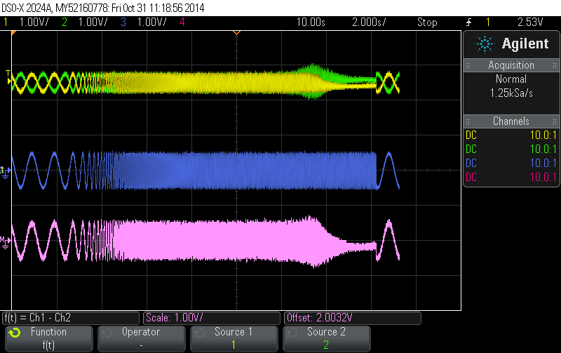
Here is what I'm seeing on an oscilloscope, i'm using a function generator with a log sine sweep.  I'm using the PGA281 evaluation module with the output filter removed, powered from +/-15V.  The negative input of the amplifier is grounded, and the sine wave is injected on the positive input.

  • Hello,

    Could you please post an image that also shows the the input signal being applied to the system? 

    The PGA281 contains a specification for the differential input signal EMI rejection ratio (EMIRR) that I've copied below. This specification is measured by injecting a high-frequency differential waveform to the inputs of the PGA and then determining the shift in input offset voltage, read more at  http://www.ti.com/litv/pdf/sboa128  

    Notice that input signals with frequencies up to 10MHz have less than 20dB of EMIRR.  So you'll get less than 10V/V of rejection of input stimulus to input offset voltage shift in these frequency ranges. 

    By connecting a large single-ended input to only one of the input pins you're also modulating the input common-mode voltage with the input stimulus.  This will also translate to a changing input referred offset voltage based on the CMRR of the PGA281 which is also very low for frequencies above the bandwidth of the product

    The only way to solve these issues will be to limit the bandwidth of the input signal to prevent such a large amplitude high-frequency waveform from reaching the inputs of the PGA281.  The input filter on the PGA281EVM is not populated by default.  Try populating the filter with values that limit the input signal bandwidth to what's needed for your application and re-run the test. 

  • With the input (blue trace).  The signal is centered around 0.  Populating the input filter doesn't do much at 100kHz to 1MHz without distorting the input signal as well.

  • Hi,

    the PGA281 is specified to a GBP of 6MHZ; altough it is noch reached yet, in your measurments theoratically, it might be the restricting thing already.

    Take a loot at fig. 16 in the datasheet, gain vs. frequency for different gains?, dont know how to exactly read it but it fits quite perfectly on to your measured results, dont you think so?