This thread has been locked.

If you have a related question, please click the "Ask a related question" button in the top right corner. The newly created question will be automatically linked to this question.

INA195 overcurrent

Other Parts Discussed in Thread: INA195

Hello,

I am using the INA195 current shunt monitor to measure the current draw of a 24VDC motor.  I use a 30mOhm shunt resistor to measure typical motor currents of 1.2A.  The supply voltage of the INA195 is +5V.

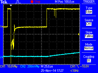
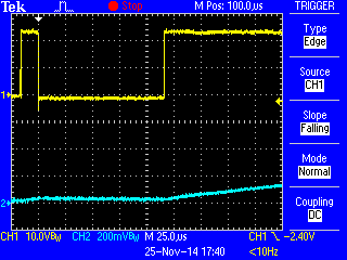
At startup, the motor will draw 12A to 14A inrush current which will saturate the output of the INA195.  I am curious if this can damage the monitor IC?  I have had problems with the current monitor IC no longer working, i.e. outputting 0V while the motor is operating.

Thanks,

Karl

  • Karl,


    14A across 30mOhm is only 0.42V across the VIN+ and VIN- inputs.  This is well within the absolute maximum spec of +18V to -18V.  With a 5V supply, this would simply mean the output would saturate to about 5V as you see, but no damage should occur (data sheet, page 2, and data sheet, page 10, output voltage range).

    Is it possible that current is being forced into the device during the inrush stage?  The maximum input current to any pin is 5mA, after which damage can occur (data sheet, page 2).

    Are the devices permanently damaged or do they recover after a power cycle?  Is there filtering or any transient protection on the inputs?  Does the board recover if the device is replaced?  How often does this damage occur?  Please share a schematic with me, either here or to my email (bridgmon_jason@ti.com) to preserve privacy if you need.

    Thank you,

    Jason Bridgmon

  • Hi Jason,

    Thanks for your response.  I have sent you a copy of the schematic and more information to your email address that you had provided.

    Regards,

    Karl

  • Hi Karl,

    Please send me a copy as well.

  • Hi Nicolle,

    I've attached the schematic.

    6254.INA195-SCH.pdf

    The motor is connected to J1 and is turned on or off by relay KR1, which is controlled by Q10.

    Here are my answers to Jason's questions:

    I don’t expect there is any current being forced into the device during inrush.

    Once the devices fail, they don’t recover after a power cycle.

    I do have the filter circuitry included as shown, but I don’t believe it is needed.  The thought was to include the components and then replace the input resistors R59 and R60 with 0Ω resistors and not install C64 if the filter isn’t necessary.

    The filter components are currently installed.  One item to note is that on at least two boards that have had device failures, I had noticed that R60 was discolored in a way that seemed to suggest that the wattage was exceeded.  These resistors are 1/8W 0805 chip resistors.  It may be that the INA195 failed and pin 4 (VIN-) was internally shorted to GND.  Not sure, but I have noticed a discolored R60 on two units.

    After the device is replaced, the board does work as expected.  However, I have had replacement devices fail after working initially.

    Any help is appreciated.  I'm beginning to suspect inductive kickback when the relay is de-energized and will need to add a freewheel diode in parallel with the motor.

    Any help is appreciated.

    Thanks,

    Karl

  • Hello Karl,

    I agree that it is most likely kick back.  Another option for protection in a trans orb at Vin+/- to keep the voltage below the ABS max.  The parallel diode should to the trick but if it doesn't this is another option.

    Regards,

    Jamieson Wardall

    Sensing Applications

  • Hi Jamieson,

    I have attached scope traces showing the motor voltage transients.  Ch.1 is the voltage at J1-pin 1 on the attached schematic (10V/div).  Ch.2 is the motor current (2A/div).

    The first image shows motor turn on without the parallel diode. (trigger level is at -10V)
    The second image shows motor turn on with a parallel diode.  Note the trigger level is reduced to -2.4V. This is the level that the scope would actually capture the spike.  If the trigger were less, say -2.8V the event would not trigger.

    6281.INA195-SCH.pdf

    I'd be interested in your thoughts.

    Regards,

    Karl