This thread has been locked.

If you have a related question, please click the "Ask a related question" button in the top right corner. The newly created question will be automatically linked to this question.

Help with Pickup Coil Amplification

Other Parts Discussed in Thread: INA118, INA326, TPS65130

Hi,

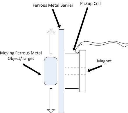
I am trying to amplify a signal that is being produced by a magnet and pickup coil and I eventually want to use this signal to trigger a 555 timer in monostable mode later in the signal chain.  I am using this arrangement to sense the movement of a metallic object as shown in the diagram below:.

I am approaching this using an instrumentation amplifier circuit (attached) and am not getting the expected output from the amplifier.

1. Am I applying the amplifier correctly given that my input/source is floating?

2. Is it appropriate to tie the REF pin to ground in this situation?

3. Am I even using the best part for this application?

4. What else am I doing wrong?

A few more details:  My input signal frequency range is approx. 1Hz - 500Hz (depending on the speed of the object).  I would like to retain the variable gain feature of the instrumentation amplifier so as to adjust the "sensitivity" of detection.

Thanks in advance!

3527.sim1.TSC

  • Here's the diagram referenced in the original post and a scope capture of the output of the coil as the object passes by:

  • Hello cliven,

    With a single 3V supply, the input common-mode range of the INA118 is 1.1V to 2V. Since both sides of your resistor divider are grounded it looks like you're violating this specification.

    So, I would start by trying the following:

    1) use dual supplies (try +/-15V supplies).
    2) disconnect everything from the output to remove other design variables.
    3) replace the potentiometer with a fixed value resistor for testing. This removes potential capacitance issues with the potentiometer.

    Hopefully that yields reasonable results. If so, you can then try adding in the potentiometer and re-connecting the output.

  • Hi Pete,


    Thank you for your suggestions.  Using dual supplies definitely made things start to make more sense in the simulation.

    Is there a way to make this circuit work with a single supply?  My application has an input voltage range of 3-24VDC and I was hoping to keep it simple by using an LDO for power.

  • Hello cliven,

    Can you please clarify what you mean by '...input voltage range of 3-24VDC'?  Is that the common-mode or differential signal?  I ask because in your simulation the differential voltage (VG1) appears to be only 20mVpp.  Unless perhaps you're talking about your supply voltage (V1).

    There are a couple options for this using a single supply.  First, you could consider the INA326, which is a RRI/O instrumentation amplifier.  It does not have the same output swing dependence on common-mode, supply, and reference voltage that traditional 3 op amp instrumentation amplifiers have (like the INA118).

    Another option is to consider using the TPS65130.  That device outputs +/-15V given a 2.7V-5.5V input.  

    A 3rd option would be to ac couple your input signal and sum it with a known common-mode voltage.  This option could be tricky given your frequency range and would require additional components to generate the common-mode voltage.  

    So my recommendation is to either consider the INA326 or use the TPS65130.  Note that if you switch to the INA326, be sure to prototype using a PCB instead of protoboard because the device is sensitive to parasitic capacitances.

  • Cliven,

    Is the barrier ferrous of non-ferrous? non-ferrous should give a much larger signal.
    Output amplitude should vary with object speed so simple large AC gain should work even if it clips with fast speed.

    This will be good enough if you need to only know the frequency. If the phase of the output matters then it might be worth the extra effort of variable gain.