


Hi,
I connect a very simple circuit on breadboard as follows just to verify
whether the opamp works well. Opamp is THS4521SHKQ

Input voltage is DC 2V and AC 10mV.
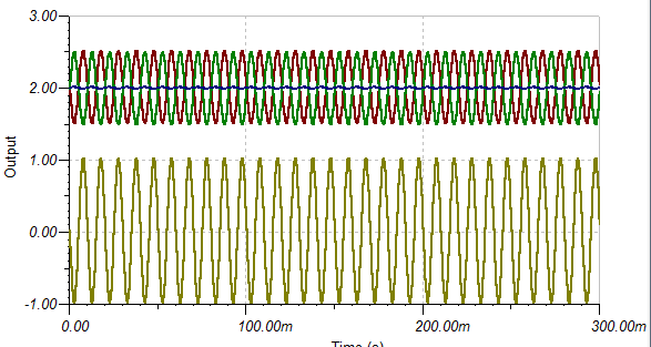
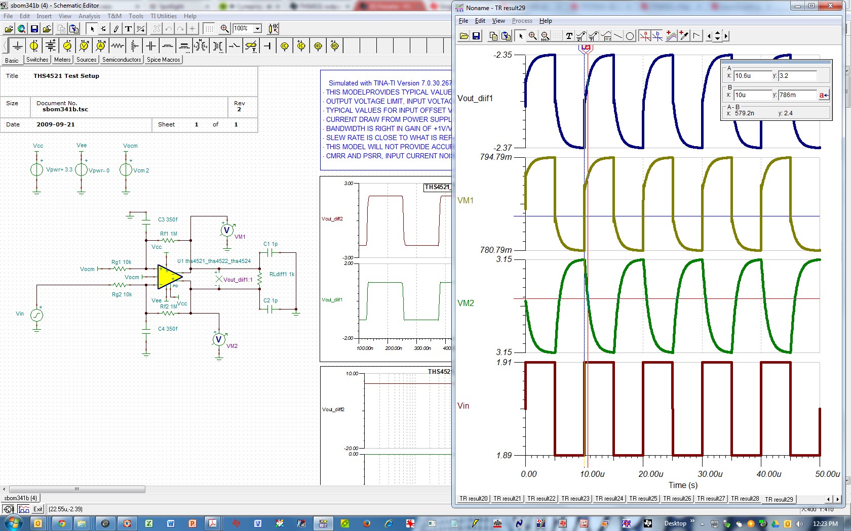
I also did a simulation in TINA, output should be as following:
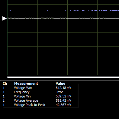
However, when i did actual measurement on the IC on the PCBA, using oscciloscope, i see below result:
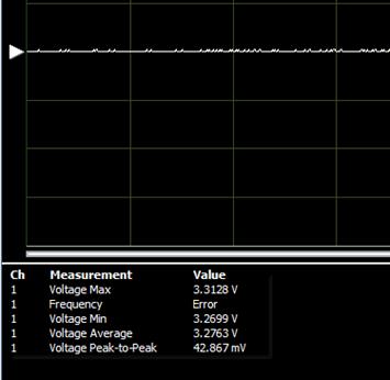
VF1 is a DC voltage around 3.27V.

VF2 is a DC voltage around 570mV.
Pls help to advise if anything wrong with the design if not, then would have to send the IC in for FA.
This is another circuit design also does not seem to have amplification:

Thanks.

