This thread has been locked.

If you have a related question, please click the "Ask a related question" button in the top right corner. The newly created question will be automatically linked to this question.

LMH5401 as a comparator

Other Parts Discussed in Thread: LMH5401

Please comment on the following:

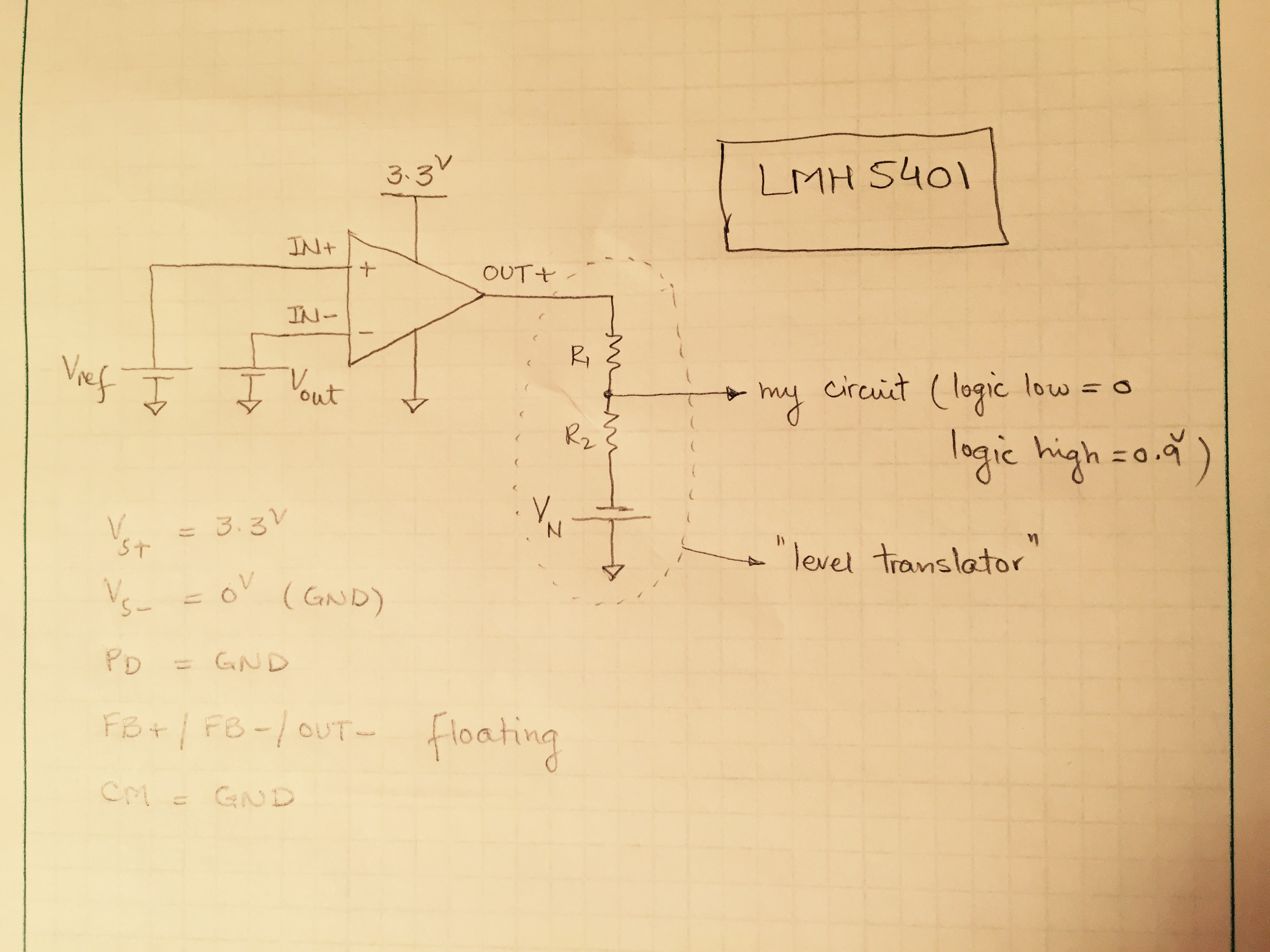
I would like to use LMH5401 as a comparator by applying my two signals to IN+ and IN- pins and looking at OUT+ and use the output network as shown below to adjust my output levels to the desired logic levels.

VS+ @ 3.3 V

VS- @ GND (0 V)

PD / CM @ GND

FB+ / FB- / OUT- @ not connected

  • Hello Artin,

    The LMH5401 was not designed to operate open loop. Also, the CM pin needs to be set to a voltage closer to the mid supply voltage of 1.65V.

    If some hysteresis is OK you could set it up for a high gain (like 20V/V or 40V/V). You may want to download the TINA reference model and try it.


    Regards,
    Loren
  • Thank you, Loren!

    What do you think about the attached architecture and component values (mainly resistors) for my application?

    I will be happy to send you the TI-TINA file, if you provide me with an email address. If you are still with TI, you can probably refer to the ticket 1-1647052574 that I submitted to the TI technical support.

    Thanks,

    ADM

  • Hello Artin,
    It looks to me like the gain is still too low. Try reducing R8,R9, R11,R12 and R15,R16 to 100 Ohms. I think you can get rid of at least one stage of LMH5401 as well. I simulated using only two LMH5401 devices and a triangle input signal gave a square wave out.
    Just to be clear, though. The LMH5401 was designed for linear operation, it was never intended to switch from saturated states continually. I do not know what happens when you use the part in this manner. We did overdrive recovery tests, so I know that occasional overdrive won't cause problems, but we never did any testing using the device as a comparator.
    Regards,Loren

  • Thanks, Loren, very much to be looking into this.

    1- My input differential signal is 5-20 mV p-p, that's why I want to have a very large gain to make sure that the system saturates. Also, I tried to keep the gain for each stage around 4V/V not to affect the bandwidth and introduce unwanted phase delays, etc. That's how I ended up with four stages: ~4x4x4x4 gain. Please let me know if it makes sense.
    2- Could you please let me know the reason you inserted an R-C in between INN and INP?
    3- Also, what would be the advantage of having an unsymmetric gain?
    4- My output stage accepts a ground-referenced signal, so I have to use either OUTP-GND or OUTN-GND signal as the actual output of my system (DiffAmp train) and scale that voltage to move from 0 V (logic low) to 0.9 V (logic high).
    5- What would be the disadvantge/advantage of using kiloOhm-range resistors versus Ohm-range as I see in the datasheet? I used the former, to minimize the loading of the DiffAmp train on the input stage of the "comparator." I hope the big resistors will not cause LMH5401 to malfunction.

    Regards,
    ADM
  • Hello Artin,


    1.  The gain of 4 will indeed not impact bandwidth, however, driving the amplifier into saturation will guarantee phase delays.   Also, cascaded stages add delay and reduce bandwidth, so it is best to use as few stages as possible.  I think you will need, at most three, stages.  Do you need a high impedance input? 

    2.  The Extra R and C are to help with stability due to the large value of Rf.   Large values of feedback resistor introduce a delay in the feedback response.  In this case I set the R to a very large value so it appears that these components may not be necessary.  I would include provisions for them in a prototype just to be safe.

    3.  That was a mistake in my part, the gain should be symmetrical.  I fixed the circuit. 

    4.  The best method to ground reference the outputs would be to use a split supply on the LMH5401 so that the amplifier output could swing to the desired voltage.

    5.   Large feedback resistors are not a good idea on high speed amplifiers.  The LMH5401 can easily drive hundred Ohm loads, especially if linearity is not a concern.

    I corrected the schematic. Three stages may be necessary if you want high impedance on the first stage, otherwise two stages looks OK. 

    1373.LMH5401_Comparator[1].TSC